USER HANDBOOK 1.0 | DC2115, ET2115
Berghof Automation GmbH | Harretstrasse 1 | 72800 Eningen | www.berghof.com
21-0099-82-00-00-003 | 270010900_Anwenderhandbuch_DC-ET2115_EN.docx
26
5.2.3. Digital inputs and outputs (DC2115)
The digital outputs are positive switching 24 V outputs with an output current of max. 500 mA. They have a
common reference potential (GND) with the supply voltage.
NOTE
Damage to the inputs or to the device!
Voltages over ±32 V can damage the inputs or the device.
No voltage in excess of ±32 V may be present at the inputs.
The digital inputs are type 1 or 3 (IEC 61131-2) positive switching inputs of type 1 or 3 (IEC 61131-2). They are
designed for nominal input voltages of 24 V. The input signals are transmitted internally on a cyclical basis
for process data processing. An open input is interpreted as static 0. The inputs also have a common refer-
ence potential (GND).
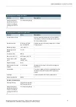
The following counterparts have been tested with the S2C-SMT 3.5 (Weidmüller) connector and are ap-
proved for use with the device:
B2CF 3.50/12/180F
Fig. 12: Digital inputs and outputs, DC2115 connector X1 with LEDs 1 to 8
Digital inputs and outputs, connector X1
Pin
Desig-
nation
Assignment
1
DO 1
digital output
2
DI 1
digital input
3
DO 2
digital output
4
DI 2
digital input
5
DO 3
digital output
6
DI 3
digital input
7
DO 4
digital output
8
DI 4
digital input
9…12
–
Power supply (see "Power supply")


