


9. The position of the dryer in the compressed air distribution system depends on the methods of use of the
compressed air (see installation drawing).
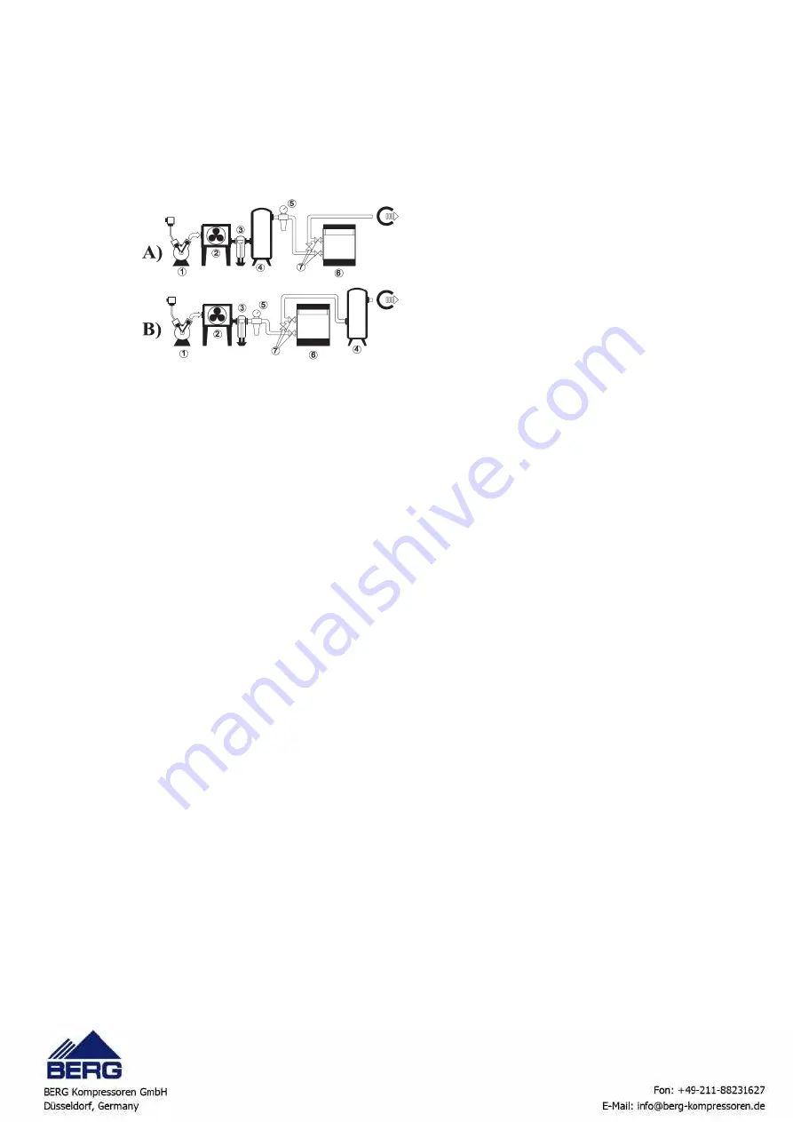
A The dryer must be installed downline of the tank when the air compressor runs intermittently and the
maximum compressed air working flow rate is no higher than the flow rate delivered by the compressor (this is
the most common type of installation).
B The dryer should be installed upline from the tank when it is sized in order to allow wide fluctuations of the air
flow rate utilized with peak values that are significantly higher than the maximum flow rate of the compressor.
5 . 2
P i p e l i n e s
(see installation drawing)
1. The inlet and outlet connections are clearly marked (see Chapter 1 “General information”). Pipes and connections
must be of the correct size and suitable for the working pressure. Remember to remove the protective caps from
the connections. and ensure that no debris or other material enters the connections during installation procedures.
Any foreign material that enters the connections can damage the exchanger irreparably.
2. If using steel pipes, it is advisable to install a magnesium anode on the line to prevent problems of corrosion on
the aluminium exchanger.
3. All pipelines must be equipped with suitable supports.
Flexible connections are recommended to avoid pipe
stress or the transmission of vibration.
4. Make suitable arrangements so that the condensate discharge pipe drains to a suitable point. The dryer drain must
not be connected to the drains of other equipment; ideally, the dryer should drain into an open funnel. Do not route
the condensate to a common drain header because of the possibility of oil contents. We recommend the use of oil/
water separators for the collection of discharged oil. Ensure that the drainage system complies with all local
regulations.
5. Install shut-off valves on the compressed air inlet and outlet connections so that the dryer can be isolated if
necessary.
Fit as suitably sized pressure relief valve upline from the shut-off valves.
6. Install a bypass line with shut-off valves so that dryer maintenance operations can be carried out without
interfering with the compressed air supply.
7. Pipelines and other parts whose temperature may exceed 60 °C (140 °F) and that may be accidentally touched by
personnel must be protected or insulated.
8. In order to discharge the compressed air from the dryer so that the unit can be depressurized prior to maintenance
operations, fit a venting valve in the pipe between the dryer and one of the two shut-off valves.
5 . 3
E l e c t r i c a l c o n n e c t i o n s
The unit’s connection to the power supply must be made in compliance with laws and prescriptions in force in the place of
installation, after having consulted the electrical diagram supplied with the plant.
The power input voltage must not surpass the tolerance limits shown on the electrical schematic, even momentarily; the
frequency and number of phases must comply with the indications on the unit’s data plate.
Unless otherwise specified, the frequency tolerance is +/-1% of the nominal value (+/-2% for short periods).
Voltage must be supplied between phase and neutral and the neutral conductor must be connected to earth in the factory
substation (TN system to IEC 364) or by the electricity company (TT system to IEC 364).
The positions of the phase conductor and the neutral conductor must not be switched.
1. air compressor
2. after-cooler
3. condensate separator
4. compressed air receiver
5. pre-filter
6. dryer
7. isolating valve