134
Installation
6003480_0 – 27.03.2017
3.5.5
Connect accessories
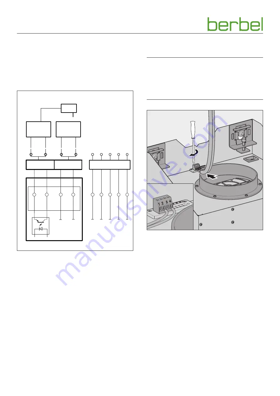
Depending on the installation situation, accessories may be
connected to the hood:
y
Wall box
y
Window contact switch
y
Under-pressure monitor
Observe the instructions for the accessories.
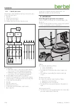
12 V DC
4
5
6
7
8
9
BMK-F
F-K
2
3
1
D
A
B
C
E
F
G
H
12 V DC
GND
X1
X1
X1
X1
X1
+ 5
V
MFK
MFK
BMK2
BMK1
ST3
+
+
–
–
I
A Control box
y
BMK1: Wall sleeve contact, optocoupler collector,
max. 12 mA / 12 V DC, safe galvanic separated
y
BMK2: Wall sleeve contact, optocoupler emitter,
max. 12 mA / 12 V DC, safe galvanic separated
B Terminal “BMK-F” for the wall box connection
C Terminal “F-K” (multifunction contact) for the window
contact switch or under-pressure monitor connection
D Control line from the wall box
E Wall box
F Wall box power unit
G Window contact switch
H Control line from the window contact switch
I Bus connection
Connection is implemented via cable terminals on a
detachable connector on the fan housing.
m
ATTENTION!
Risk of damage through incorrect connection!
A mix-up of the control wires can result in damage to the
electronics.
When connecting the control line ensure correct polarity:
Core 1 on terminal 1, core 2 on terminal 2.
1.
2.
Wall box
Connect the wall box as follows:
y
Core 1 on terminal 1
y
Core 2 on terminal 2
y
The wall box is closed when the control contacts are
open.
y
The wall box is open when the control contacts are
closed.
Window contact switch
Connect the window contact switch as follows:
y
Blue/white core to terminal 3
y
Brown/green core to terminal 4
y
The hood‘s fan is only operational when the window is
open.
Under-pressure monitor
y
The hood‘s fan is only operational when no critical under-
pressure is determined in the room.
Содержание BKH 110 GL-2
Страница 152: ...6003480_0 27 03 2017 ...

