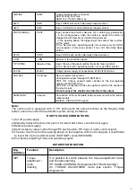
Beninca KER Скачать руководство пользователя страница 9

9

N-BLINK

LAMP

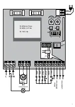
Output, flashing light connection 

KER: 230VAC 40W max.

KER 115V: 115VAC 40W max.

SWO

SWO

Input, OPEN limit switch (Normally Closed contact)

SWC

SWC

Input, CLOSE limit switch (Normally Closed contact)

PHOT(CHIUDE)

PHOT

Input, connection of safety devices, N.C. contact (e.g. photocells): 

- in the closing phase, when the contact is opened the motor is 

stopped and its direction is immediately reversed;

- in the opening phase, the triggering of the contact has no effect 

on the motor.

In the “Service man” operating mode, this contact acts as CLOSE 

control signal. In this case connect it to a N.O. (Normally Open) 

button.

STOP

STOP

Input, STOP push-button (Normally Closed contact) 

 COM

 COM

Common, for all control inputs. 

P.P (OPEN).

Step-by-Step

Input, Step-by-Step push-button (Normally Open contact)

In the “Service man” operating mode, it acts as OPEN control. 

24 VAC

24VAC

Output, power supply of accessories, 24VAC/200mA max 

SCA-SCA

Ch.II/Lock

Non-insulated, free contact. 

Configurable output through DIP-SWITCH 5.

DIP5 ON: Output, second radio channel of the incorporated 

receiver (24VAC/3W max). 

DIP5 OFF: Connection to the Lock optional card for the control of 

the electric lock. 

Do not connect the electric lock directly to the output.

SHIELD-ANT

Antenna

Connection of the extractable radio receiver card and the built-in 

radio module 

(SHIELD- DISPLAY/ANT-signal). 

Note: 

The control unit is equipped with a “P2” button with the same functions as the Step-by-Step 
button, useful to control the automatic system during installation.

HOW TO CHECK CONNECTIONS:

1) Cut off power supply.
2)  Manually release the door and push it for about half stoke. Lock the door again.
3) Restore power supply.
4)  Send a step-by-step control through P2 push-button, P.P. input or radio-control signal.  
5)  The door must move in the opening phase. In the negative, with motor stopped, it is sufficient 

to invert the motor and limit switch  (MOT/MOT) wires (SWO/SWC).

6) Proceed by adjusting Times and operating Logics.
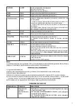
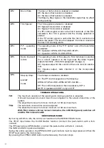
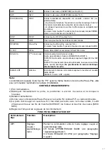
DIP-SWITCH FUNCTION

Dip-

Switches

Function

Description

DIP1

Torque 
adjustment /
radio
learning

It is possible to switch between the torque adjustment mode 
and the radio learning.
Off: RADIO LEARNING mode (see section “Radio learning”)
On: TORQUE ADJUSTMENT mode (see section “Torque 
Regulation”).

Содержание KER

Страница 1: ...L8542498 02 2013 rev 4 KER UNIONE NAZIONALE COSTRUTTORI AUTOMATISMI PER CANCELLI PORTE SERRANDE ED AFFINI...

Страница 2: ...2...

Страница 3: ...L1 DL2 N GND L LAMP 115 230Vac 40W max COM M C 24Vac 200mA max P P STOP SWO SWC PHOT COM P1 P2 SW 1 6 TW TCA U2 F3 F2 Lock 12Vac L N LOCK DIP5 OFF F3 KER230 F6 3A F3 KER115 F10A F2 F315 mA ANT SHIELD...

Страница 4: ...nte Automatismi Beninc SpA Indirizzo Via Capitello 45 36066 Sandrigo VI Italia Dichiara che il prodotto Centrale di comando per 1 motore KER conforme alle condizioni delle seguenti Direttive CE DIRETT...

Страница 5: ...ac 3W max DIP5 OFF Collegamento alla scheda opzionale Lock per il control lo dell ellettroserratura Non collegare l elettroserratura diretta mente all uscita SHIELD ANT Antenna Collegamento antenna sc...

Страница 6: ...alit 3 PASSI Abilita o disabilita la funzione 3 PASSI On La sequenza di comandi PP la seguente APRE STOP CHIUDE APRE STOP CHIUDE Off La sequenza comandi quella impostata dal DIP 4 N B funziona solo co...

Страница 7: ...D pag 7 N B tenere presente che se il dip 5 in OFF il tasto associato funziona da pedonale apertura per circa 7 secondi altrimenti con dip 5 in ON il tasto associato funziona da 2 ch sull uscita SCA P...

Страница 8: ...ia Capitello 45 36066 Sandrigo VI Italy Declares that the product Control box for 1 motor KER conforms with the requirements of the following EU Directives DIRECTIVE 2004 108 CE OFTHE EUROPEAN PARLIAM...

Страница 9: ...adio channel of the incorporated receiver 24VAC 3W max DIP5 OFF Connection to the Lock optional card for the control of the electric lock Do not connect the electric lock directly to the output SHIELD...

Страница 10: ...ard for electric lock On Impulse output radio channel II of the incorporated receiver DIP6 Step by Step 3 STEP mode The 3 steps is enabled or disabled On The PP control sequence is the following OPEN...

Страница 11: ...g in the mains power supply mode see LED diagnostics page 7 NOTE Keep in mind that if DIP5 is OFF the matched key acts as pedestrian key opening for around 7 seconds otherwise with DIP5 to ON the matc...

Страница 12: ...CE EMC 2006 95 CE LVD Hersteller Automatismi Beninc SpA Anschrift Via Capitello 45 36066 Sandrigo VI Italien Erkl rt dass das Produkt Steuerung f r 1 Motoren KER die Bedingungen der folgenden CE Rich...

Страница 13: ...Karte des steckbaren Funkempf ngers und eingebautes Funkmodul SHIELD Bildschirm ANT Signal Bemerkung Die Zentrale verf gt ber eine Taste P2 mit derselben Funktion der Taste Schritt Schritt die zur St...

Страница 14: ...tellt N B funktioniert nur mit DIP4 auf Off TRIMMER FUNKTIONEN TW Regelt die maximale Dauer der Schaltungen ffnen und Schlie en Muss um circa 4s sec l nger als die Zeit f r den tats chlichen Hub der A...

Страница 15: ...handen blinkt siehe LED Diagnostik auf Seite 7 N B Wenn der DIP 5 auf OFF geschaltet ist bernimmt die zugeteilte Taste als Fu g nger Funktion ffnung ca 7 Sekunden wenn der DIP 5 auf ON geschaltet ist...

Страница 16: ...ration en accord avec les Directives 2004 108 CE CEM 2006 95 CE DBT Fabricant Automatismi Beninc SpA Adresse Via Capitello 45 36066 Sandrigo VI ITALIE D clare que le produit Centrale de commande pour...

Страница 17: ...ptionnelle Lock pour le contr le de la serrure lectrique Ne pas brancher la serrure lectrique directement la sortie SHIELD ANT Antenne Branchement antenne carte radio r cepteur insertion et module rad...

Страница 18: ...Lock pour serrure lectrique On Sortie impulsive 2 me canal radio Du r cepteur int gr DIP6 P P Modalit 3 PASSI Active ou d sactive la fonction 3 PAS On La s quence des commandes PP est la suivante OUVR...

Страница 19: ...de tension voire diagnostique LED page 7 N B il faut se rappeler que si le dip 5 est sur OFF la touche associ e fonctionne en tant qu acc s pi ton ouverture pendant 7 secondes environ sans quoi avec l...

Страница 20: ...c SpA Direcci n Via Capitello 45 36066 Sandrigo VI Italia Declara que el producto Central de mando para 1 motor KER es conforme a las condiciones de las siguientes Directivas CE DIRECTIVA 2004 108 CE...

Страница 21: ...corporado 24 Vac 3W max DIP5 OFF Conexion a la tarjeta opcional Lock por el con trol del electro cerradura No conecten directamente el electro cerradura a la salida utilizar LA TARJETA LOCK SHIELD ANT...

Страница 22: ...ASOS On La secuencia de mandos PP es la siguiente ABRE STOP CIERRA ABRE STOP CIERRA Off La secuencia de mando es la programada por el DIP 4 N B funciona s lo con DIP 4 en OFF Funci n de los Trimmer TW...

Страница 23: ...tecla asociada funciona como peatonal abertura por unos 7 segundos de otro modo con dip 5 en ON la tecla asociada funciona de 2 ch sobre la salida SCA Por reiniciar la memoria del receptor pulsar y ma...

Страница 24: ...s Via Capitello 45 36066 Sandrigo VI W ochy O wiadcza e maszyna Centralka sterowania 1 silnika KER spe nia wymogi nast puj cych dyrektyw WE DYREKTYWA 2004 108 WE PARLAMENTU EUROPEJSKIEGO I RADY z 15 g...

Страница 25: ...ego wbudowanego odbiornika 24 Vac 3W max DIP5 OFF Po czenie z opcjonaln kart Lock do kontroli elektrycznego zamka Nie pod cza elektrycznego zamka bezpo rednio do wyj cia SHIELD ANT Antena Po czenie an...

Страница 26: ...Wyj cieimpulsowedokontrolikartyLockelektrycznego zamka On Wyj cie impulsowe II kana u radiowego wbudowanego odbiornika DIP6 P P Tryb 3 KROK W W cza lub wy cza funkcj 3 KROK W On Sekwencja polece PP je...

Страница 27: ...j cia z trybu programowania bez zapisywania adnego zdalnego pilota nacisn klawisz P1 do chwili gdy czerwona dioda DL1 zacznie ponownie miga w trybie obecno ci sieci zobacz diagnostyka diod LED str 7 N...

Страница 28: ...AUTOMATISMI BENINC SpA Via Capitello 45 36066 Sandrigo VI Tel 0444 751030 r a Fax 0444 759728...

Отзывы: