


11
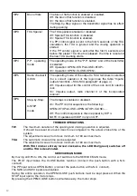
TORQUE REGULATION (DIP1:ON)
When DIP1 is moved to ON, the card indicates the torque applied at that moment through a
number of flashes (from 1 to 4) of the DL2 green LED, followed by a 3 sec interval.
The maximum torque is indicated with the DL2 green LED with fixed light.
To increase the torque, press the P1 key. The DL2 LED changes the number of flashes to indicate
the selected torque value.
Once the desired torque is selected, to learn this setting move the DIP1 to OFF.
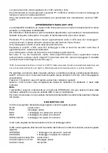
RADIO LEARNING (DIP1:OFF)
The KER control unit is equipped of a built-in radio module for the reception of variable code,
with 433.92 MHz frequency.
To use a remote control, its code must be stored in memory. The memorisation procedure is
shown hereunder. Up to 64 different codes can be stored in the memory of the device.
By pressing the P1 key, the control unit enters the radio self-learning phase: the red DL1 LED
flashes 1 time per second, awaiting for the key to be matched to the Step-by-Step function;
Once the key is learned, exit from the programming mode;
By pressing the P1 key twice, the red DL1 LED flashes two times per second and enters the
learning mode of Channel 2, radio/pedestrian*.
Once the key is learned, exit from the programming mode.
To exit the programming mode without learning any radio control code, press P1 key until the red
DL1 LED returns flashing in the “mains” power supply mode (see LED diagnostics, page 7).
* NOTE: Keep in mind that if DIP5 is OFF, the matched key acts as pedestrian key (opening for around 7
seconds), otherwise, with DIP5 to ON, the matched key operates as 2nd channel on the SCA output.
To reset the receiver memory, press P1 and P2 keys simultaneously and keep them pressed for
around 10 seconds (during this time-lapse, both DL1 and DL2 LEDs flash rapidly).
After ten seconds, the two LEDs remain switched on with fixed light. Release the push-buttons.
When the LEDs return to the initial configuration, this means that the control unit has performed
the resetting of the memory.
Note:
The transmitters are stored in an EPROM memory (U2), which can be removed and repositioned
in a new KER control unit, if required.
For safety reasons, it is not possible to store transmitter codes into memory during the opening/
closing phases of the motor.
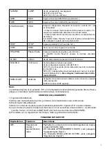
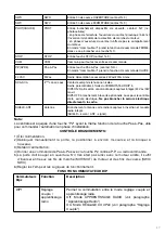
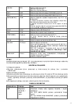
LED DISGNOSTICS
The red LED indicates the activation of inputs, according to the following legend:
STOP
fixed light
PHOT
rapid flashing
SWO
1 flash at every 2 second interval
SWC
2 flashes at every 2 second interval
OPEN+CLOSE
3 flashes at every 2 second interval
With slow flashing, the red LED indicates that the unit is powered from the mains.
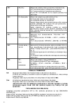
The green LED indicates the movement direction of the motor and the status of the gate according
to the following legend:
OPENING
1 flash at every 1 second interval
CLOSING
2 flashes at every 1 second interval
Open gate without TCA
fixed light
Open gate with TCA
rapid flashing
Closed gate
LED off