


BE2c
36
7/8”
Page
5
Copyright©
2007
‐
11
M.K.
Bengtson
All
Rights
Reserved
Rev
07/11
Fuselage
Construction
The
fuselage
is
built
in
two
sections,
a
front
half
and
a
rear
half
which
are
then
joined
over
the
plan.
This
simplifies
construction
and
helps
ensure
a
straight
fuselage.
Cowl
Glue
parts
C1
and
C2
together.
The
‘top’
(flatter)
surfaces
and
sides
are
flush,
the
lower
(more
rounded)
surfaces
are
stepped
for
later
sanding
to
the
profile
on
the
plans.
Front
Section
Start
by
pinning
one
1/8”
balsa
fuse
side
to
the
side
view
plan
and
epoxy
FCB
and
RCB
carbane
struts
into
their
slots
in
the
fuse
side.
Note
FCB
and
RCB
are
different.
Ensure
everything
is
precisely
over
the
plan
and
the
structure
stays
flat
while
the
glue
sets.
Wing
alignment
will
later
depend
on
the
accuracy
of
this
assembly.
Epoxy
FCB
and
RCB
into
fuse
side.
When
the
glue
has
completely
hardened
on
the
first
side,
either
remove
it
and
repeat
for
the
second
side,
or
build
the
second
side
over
the
first
with
a
piece
of
cling
wrap
in
between
so
the
two
don’t
glue
together.
Either
way
the
intent
is
to
achieve
2
identical
sides
with
the
carbane
struts
aligned
and
vertical.
There
is
no
left
or
right
side
to
worry
about
here
they
are
the
same.
While
the
second
side
sets
locate
parts
F2,
F6,
F1D
and
cut
the
1/8”x1/4”
cross
braces
in
preparation
for
joining
the
fuse
sides.
Cleaning
out
the
U/C
lacing
holes
in
F1D
(and
F1C)
with
a
1/16”
drill
will
be
easier
now
than
later.
Forming
the
basis
of
the
front
fuse
section
begins
with
pinning
F1D
to
the
plan
view
over
it’s
location
(note
orientation
–
lacing
holes
to
the
rear).
Using
epoxy,
attach
the
two
fuse
sides
with
F2
and
F6
between,
to
F1D
and
then
the
cross
braces
to
the
top.
Take
time
at
this
stage,
and
use
straight
edges
and
squares
to
ensure
everything
is
dead
straight
and
square
and
that
the
carbane
struts
and
fuse
sides
are
vertical
to
the
building
surface.
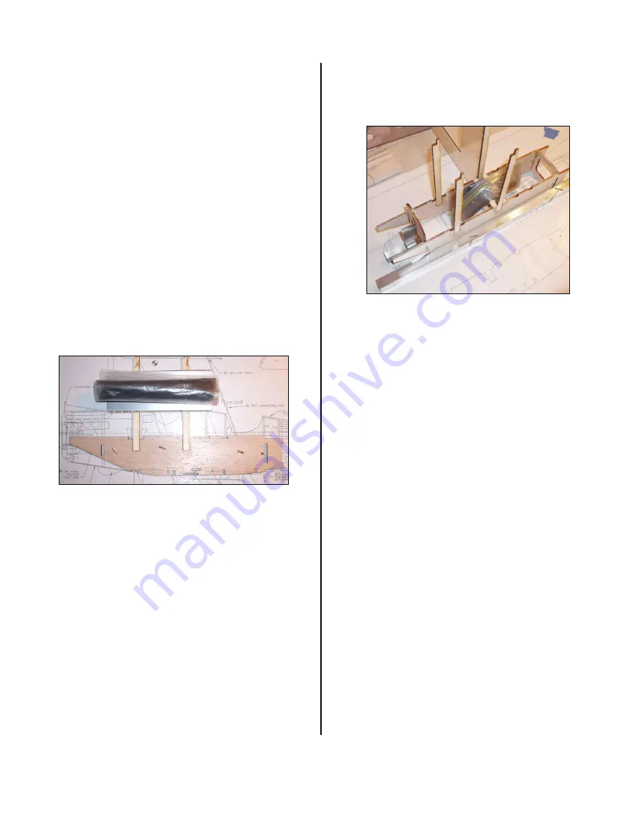
Main
fuse
parts
setting.
(Small
bag
of
shot
weighing
things
down)
The
rest
of
the
fuse
formers
etc
can
be
glued
in
after
the
trueness
of
the
basic
structure
has
been
achieved.
Now
the
plan
side
view
has
been
vacated
construction
of
the
tail
lattice
could
begin
while
the
epoxy
sets
in
the
front
half.
See
Tail
Section
below.
When
the
basic
front
structure
has
completely
set,
continue
adding
the
remaining
formers
F1,
F3,
F4
and
F1C
(lacing
holes
to
the
front).
Check
F1
is
vertical,
with
the
fuse
on
its
‘flat’
(ie
F1D
is
flat
to
the
building
surface).
Check
carbane
struts
remain
true
when
attaching
the
four
F3
formers
either
side
of
these
struts.
Note
the
formers
F3
&
F4
are
narrower
than
the
overall
width
of
the
fuse
sides
to
allow
for
the
later
1/16”
sheeting
of
the
upper
half,
ensure
they
are
evenly
spaced
either
side.
Install
the
motor
mount
3/8”
square
stock,
use
the
plans
to
help
establish
the
2
‐
3
degree
right
and
down
thrust
angles.
Complete
this
stage
by
gluing
in
the
four
servo
mounting
rails
as
indicated
on
the
plans.
Allow
glue
to
set
completely.
Next
the
fuse
sides
need
to
be
scored
and
cracked
behind
F6
to
taper
the
sides
to
the
narrower
F7.
After
scoring
the
insides
of
the
sides
just
behind
F6,
locate
the
fuse
over
the
plans
and
bend/crack
the
sides
behind
F6
inwards
evenly
to
conform
to
the
width
of
F7
keeping
it
all
aligned
and
positioned
with
the
plans.
Glue
and
temporarily
tape
F7
to
the
sides.
Glue
reinforces
your


