Bender COMTRAXX MK2430 Скачать руководство пользователя страница 25

Installation and connection

25

MK2430_D00129_02_M_XXEN/09.2019

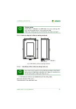
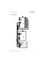
4.2.3 Dimension diagram surface-mounting enclosure

Fig. 4.2: MK2430 in surface-mounting enclosure
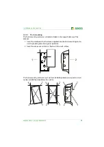
4.2.3.1

Installation of the surface-mounting enclosure

 

Use the empty enclosure as a template to mark the drilling holes.

Maximum diameter of the screws: 
Thread of screw: 3 mm, bolt head: 7 mm.

Screw mounting

The MK2430S-11, MK2430S-12 and MK2430H-12 versions are designed for
screw mounting. MK2430H-12 is mounted horizontally.
When screw mounting, make sure that the front panel does not bend!

A smooth and even surface is a precondition for installation. Only the fas-
tening screws specified below should be used. Failure to observe this can
result in deformation or damage to the enclosure.

MK2430A

MK2430

Содержание COMTRAXX MK2430

Страница 1: ...Manual EN COMTRAXX MK2430 Alarm indicator and test combination Software version 4 1x MK2430_D00129_02_M_XXEN 09 2019...

Страница 2: ...ndorfer Str 65 35305 Gr nberg Germany Tel 49 6401 807 0 Fax 49 6401 807 259 E mail info bender de www bender de Bender GmbH Co KG All rights reserved Reprinting and duplicating only with permission of...

Страница 3: ...1 5 Inspection transport and storage 9 1 6 Warranty and liability 9 1 7 Disposal 10 2 Safety instructions 11 2 1 General safety instructions 11 2 2 Work activities on electrical installations 11 2 3 I...

Страница 4: ...on of the surface mounting enclosure 25 4 3 Connecting the device 26 4 3 1 Safety instructions 26 4 3 2 Notes on the connection 26 4 3 3 Wiring diagram 27 4 3 4 Connection assignment 29 4 3 4 1 MK2430...

Страница 5: ...agram 55 8 3 Main menu functions 56 8 4 The main menu 56 8 4 1 Exit 56 8 4 2 Menu 2 History 57 8 4 3 Menu 3 Settings 58 8 4 3 1 Exit 59 8 4 3 2 Settings menu 2 Alarm addresses 60 8 4 3 3 Settings menu...

Страница 6: ...ontrol menu 3 EDS Start Stop 71 8 4 4 4 Control menu 4 Test communication MK2430 11 only 71 8 4 5 Menu 5 External devices 72 8 4 6 Menu 6 Info 73 8 5 Overview of setting options 73 9 Technical data 75...

Страница 7: ...aken in the drafting of this operating manual it may nevertheless contain errors and mistakes Bender cannot accept any liability for injury to persons or damage to property resulting from errors or mi...

Страница 8: ...oducts Hardware and software update for Bender devices Delivery of replacement devices for faulty or incorrectly delivered Bender devices Extended warranty for Bender devices with in house repair serv...

Страница 9: ...software clause in respect of the licensing of standard software as part of deliveries modifications and changes to general delivery conditions for products and services in the electrical industry se...

Страница 10: ...st be observed 1 7 Disposal Abide by the national regulations and laws governing the disposal of this device Ask your supplier if you are not sure how to dispose of the old equipment The directive on...

Страница 11: ...ectify any faults that may endanger safety Do not make any unauthorised changes and only purchase spare parts and optional accessories recommended by the manufacturer of the devices Failure to observe...

Страница 12: ...equipment can be tested using the programmable TEST button Important display functions Normal operation indicator green LED Insulation fault Overload Overtemperature Messages from EDS insulation faul...

Страница 13: ...cal equipment to be recorded and displayed on the MK2430 for example from medical gases or battery supported safety power supply systems BSV systems MK2430 are used in Healthcare facilities Industrial...

Страница 14: ...Safety instructions 14 MK2430_D00129_02_M_XXEN 09 2019...

Страница 15: ...ion 3 1 MEDICS The MK2430 alarm indicator and test combinations are integral components of the MEDICS system MEDICS is an intelligent system that guarantees safe power supply in medical locations Exam...

Страница 16: ...s for the MEDICS system are UMC USC UFC and or EDS insulation fault loca tion systems Communication between these components via the BMS bus two wire connec tion The connection of third party systems...

Страница 17: ...ult Circuit Interrupters A message will only be displayed on the MK2430 on which the TEST button has been pressed The test and its individual evaluations are carried out sequentially Finally a message...

Страница 18: ...owledging or muting alarms and warnings testing assigned devices and for the menu system 3 3 2 Programmable messages Standard message texts can be activated by enabling alarm addresses These texts are...

Страница 19: ...figurable The voltage required for these inputs is provided via the power supply unit which also supplies power to the MK2430 Any message text can be assigned to the inputs 3 4 3 MK2430C The MK2430C i...

Страница 20: ...the MK2430 to a PC directly via the USB interface or via an RS 232 RS 485 converter DI 2 or a USB RS 485 converter DI 2USB to the BMS bus You can use the optional TMK SET PC software to display and ch...

Страница 21: ...l injury due to electric shock Touching live parts of the system carries the risk of An electric shock Damage to the electrical installation Destruction of the device Before installing and connecting...

Страница 22: ...agram flush mounting enclosure Fig 4 1 MK2430 in flush mounting enclosure Front panel cutout 161 x 77 mm The MK2430 is fixed in its enclosure with brackets In addition the MK2430 can be secured in its...

Страница 23: ...ope of delivery of the MK2430 1 Insert the cardboard that has been supplied into the flush mounting enclo sure to provide protection against pollution 2 Insert the enclosure so that it is flush with t...

Страница 24: ...eans of the mounting brackets attached on each side the MK2430 snaps into the flush mounting enclosure Two mounting brackets M are used for additional support Theyareneeded inparticulariftheMK2430hast...

Страница 25: ...s Maximum diameter of the screws Thread of screw 3 mm bolt head 7 mm Screw mounting The MK2430S 11 MK2430S 12 and MK2430H 12 versions are designed for screw mounting MK2430H 12 is mounted horizontally...

Страница 26: ...voltage Us a 4 wire cable 2 x BUS 2 x Us with suitable cross sec tion is required Set the terminating resistor for the BMS bus on the Term DIP switch Factory set ting off MK2430 11 only Use cables wi...

Страница 27: ...Installation and connection 27 MK2430_D00129_02_M_XXEN 09 2019 4 3 3 Wiring diagram ATICS isoMED 1 2 3 4 5 6 1 6 7...

Страница 28: ...CMS470 can be connected to the BMS bus 3 Power supply unit in the MEDICS module sufficient for supplying power to at least three MK2430 4 Cable between the MEDICS module and the MK2430 Please observe...

Страница 29: ...427P 107TD47 an MK2430 11 a signal converter SMI47x an EDS or an RCMS for example U2 V2 Supply voltage Us looped through connection for supply voltage Us Note Make sure that the power supply of the MK...

Страница 30: ...y on page 62 4 4 Examples for BMS bus connection and addressing IN1 IN12 Digital inputs 1 12 0 IN1 4 Common connection 0 for digital inputs 1 4 0 IN5 8 Common connection 0 for digital inputs 5 8 0 IN9...

Страница 31: ...monitoring module 107TD47 Bus address 3 PRC487 Bus address 4 Second UMC107E changeover and monitoring module 107TD47 Bus address 5 PRC487 Bus address 6 Alarm indicator and test combinations First MK2...

Страница 32: ...474 12 Bus address 61 Second UFC107E changeover and monitoring module 107TD47 Bus address 5 PRC487 Bus address 6 PGH474 Bus address 112 EDS474 12 Bus address 62 Alarm indicator and test combinations F...

Страница 33: ...30_D00129_02_M_XXEN 09 2019 Third MK2430 Bus address 7 Test address 3 5 Alarm address 1 2 3 4 5 6 8 61 62 111 112 Fourth MK2430 Bus address 8 Test address 3 5 Alarm address 1 2 3 4 5 6 7 61 62 111 112...

Страница 34: ...4 Second changeover and monitoring module ATICS B Bus address 5 EDS151 B Bus address 6 Alarm indicator and test combinations First MK2430 Bus address 1 Test address 3 5 Alarm address 2 3 4 5 6 7 8 Sec...

Страница 35: ...ne MK800 Device Parameter Address settings Residual current monitors 1 RCMS460 Bus address 3 2 RCMS460 Bus address 4 3 RCMS460 Bus address 5 Alarm indicator and test combinations MK2430 Bus address 2...

Страница 36: ...Installation and connection 36 MK2430_D00129_02_M_XXEN 09 2019...

Страница 37: ...ng on 3 Parameter setting Settings on the MK2430 Settings using the software TMK SET 4 Tests after parameter setting Pleasewrite downallsettings andkeep themwiththe equipmentor instal lation documenta...

Страница 38: ...ing resistors properly or switch them on use the DIP switch at MK2430 yes yes yes MK2430 11 only Do the digital inputs have the correct voltage Make corrections yes MK2430 11 only Are the digital inpu...

Страница 39: ...quired connect another or different power supply unit for MK2430 supply Did the supply voltage or the MK2430 fail Remove the fault yes Fix the MK2430 to the enclosure Does the MK2430 display a fault m...

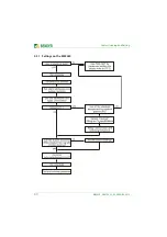
Страница 40: ...Commissioning and testing 40 MK2430_D00129_02_M_XXEN 09 2019 5 3 1 Settings on the MK2430...

Страница 41: ...Commissioning and testing 41 MK2430_D00129_02_M_XXEN 09 2019 5 3 2 Settings using the TMK SET software BSV...

Страница 42: ...l regulations that apply For your Bender products we recommend Select Test mode from the menu External devices Are all external device settings OK no make corrections Simulate fault messages e g devic...

Страница 43: ...e instructions in chapter Test of the changeover device manual changeover device have to be observed Electri cally skilled person Every six months Functional test of the IT system monitoring insulatio...

Страница 44: ...is the intervals specified for periodic verification should be adhered to 5 4 3 Cleaning and disinfection The front foil is glued in ensuring marginal fit The device is mounted without using screws al...

Страница 45: ...then switch it on again if unsuccessful Replace the MK2430 3 RTC ERROR Clock chip defective Replace the MK2430 4 FLASH ERROR Assignment chip defective Replace memory chip D15 socketed or replace MK24...

Страница 46: ...run Processor does not start Replace MK2430 Time is reset to zero in case of short term voltage failure Replace MK2430 Error during transfer of the assigned addresses or basic settings via the USB in...

Страница 47: ...g personnel 7 1 Operator control and display elements LED and LCD 1 NORMAL LED Power On indicator green is only lit when no warnings or alarms are pending 2 WARNING LED Warnings yellow 3 ALARM LED Ala...

Страница 48: ...itional text Toggle between display text and addi tional alarm text if available Arrow button to go down in the menu 7 button scroll Scroll through the warnings and alarms if there is more than one me...

Страница 49: ...itched off 7 2 2 Display in fault condition A warning or an alarm message is pending Depending on the type of fault either the yellow Warning LED or the red Alarm LED will light up The green Normal LE...

Страница 50: ...nel of device triggering the message Line 4 xx number of the message displayed yy number of pending messages alarm test page in this case page 2 17 30 time of day example zzz Meaning EDSa EDS insulati...

Страница 51: ...TEST The message TEST flashes if the message being displayed has been caused by the test The assigned devices are tested one after another The MK2430 automatically evaluates the messages that appear...

Страница 52: ...ISOMETER s e g IRDH Note 0 No messages received from the ISOMETER although the test command was confirmed by the ISOMETER No messages received from the ISOMETER although the test command was confirmed...

Страница 53: ...e displayed This information is also available in the Info menu If there are no messages pending the standard display will be shown when the starting procedure is completed The TMK SET software allows...

Страница 54: ...more than five minutes menu mode is exited automatically exception Test communication in the Control menu and Position mode in the External devices menu Some menus are password protected Password prot...

Страница 55: ...help you to navigate through the menus 1 Exit 2 History 2 Alarm addresses 1 Exit 3 Test addresses 4 Digital inputs 5 Buzzer 6 Common reset 7 Clock 8 Language 9 Interface 10 Relay 11 Password 12 Servi...

Страница 56: ...th information about mes sages acknowledgements and their timestamps 57 3 Settings Various settings for this MK2430 58 4 Control Control setting options for the overall system 70 5 External devices Se...

Страница 57: ...connection 1 Use the arrow buttons to select the entry you require The latest entry appears first on the display Older messages can be selected using the arrow buttons 2 Press the button to call up t...

Страница 58: ...enu level 2 Alarm addresses Setting bus addresses for devices so that the alarm mes sages of these devices can be displayed on this MK2430 60 3 Test addresses Setting bus addresses for devices which a...

Страница 59: ...common alarm relay alarm relay on the MK2430 11 68 11 Password Changing the password enabling disabling the password 69 12 Service menu These settings can only be made by authorised Bender serv ice pe...

Страница 60: ...K SET software If several systems or areas e g several operating theatres are connected to the MK2430 then these systems can be assigned numbers 1 4 1 Exit Back to the main menu 2 Edit table Use the a...

Страница 61: ...rm texts are a minimum requirement for Channel 1 3 setting 107TD47 Channel 1 setting IRDHxxx 1 Exit Back to the main menu 2 Edit table Use the arrow buttons to select the internal BMS bus ad dress and...

Страница 62: ...utral and specific alarm messages on page 63 Alarm texts for digital inputs A neutral or specific alarm message can be assigned to every digital input A neutral alarm message indicates the alarm the c...

Страница 63: ...tion neutral Specific alarm messages Function medical IN1 Alarm Address channelXXX 01 Alarm Oxygen IN2 Alarm Address channel XXX 02 Alarm Vacuum IN3 Alarm Address channel XXX 03 Alarm Nitrous oxide IN...

Страница 64: ...tting indicating whether this MK2430 should respond On or not Off to the acknowledgementof the buzzer buzzer mute initiated by pressing the button on another MK or TM remote alarm indicator and operat...

Страница 65: ...utomatic switchover can be deactivated menu item 5 Summertime 1 Exit Back to the main menu 2 Time Set the time hours and minutes 3 Date Set the date according to the format indicated in line 4 4 Forma...

Страница 66: ...man or English 3 Mess Select the language for the message display Choose from German English French Italian Spanish Portuguese Portuguese Brazil Dutch Norwegian Swedish Finnish Danish Polish Hungarian...

Страница 67: ...ial applications e g PC OPC and cannot be used for devices Factory setting is address 001 master 3 Baud The fixed preassigned baud rate is 9600 bit s Change the corresponding device address if several...

Страница 68: ...in case of an internal fault on the MK2430 11 Common alarm Relay switches in case of any warning or alarm message Device failure Relay switches as soon as the MK2430 recognises a device failure ISOMET...

Страница 69: ...u is only accessible after entering a master password In the service menu information about the device status can be called up and settings for specific operating conditions can be made Some menus are...

Страница 70: ...the last line This reset command is sent via the BMS bus Note that some devices e g PRC470 do not respond to this reset Menu item Function Page 1 Exit Exit Control menu go up one menu level 2 Reset A...

Страница 71: ...nt test run finishes Other abbreviations that might appear in the last line of the display EDSa Automatic mode Insulation fault location has been started on PGH47x by e g ISOMETER ATICS or isoMED427P...

Страница 72: ...cted under the address the character appears Use the arrow buttons to select the address of the external device and confirm your selection with the button If the device has been recognised the MK2430...

Страница 73: ...the alarm messages and digital inputs of the MK2430 Set parameters Select ESC Exit menu mode Show date of last assignment transmission Show version of standard texts and number of activated alarm add...

Страница 74: ...x S W time autom OFF autom M8 x Automat summer winter time Buzzer ON OFF for 1 9 hrs ON M13 x e g for commissioning Password prompt Y N Y M12 x Activate password prompt Password 000 999 807 M12 x Chan...

Страница 75: ...acters four lines 4x 20 characters Standard message texts in 20 languages Alarm addresses 150 Programmabletext messages 200 History memory messages 250 Standard text message 3x 20 characters Additiona...

Страница 76: ...pair one end of shieldconnected to PE J Y St Y min 2 x 0 8 Terminating resistor 120 0 25 W connectable via DIP switch Device address BMS bus 1 150 Factory setting device address 1 master Programming...

Страница 77: ...EMC EMC immunity acc to EN 61000 6 2 EMC immunity acc to EN 61000 6 3 Classification of climatic conditions acc to IEC 60721 Stationary use 3K5 Transport 2K3 Long term storage 1K4 Operating temperatur...

Страница 78: ...leeve 0 5 mm2 Stripping length 7 mm Tightening torque 0 5 0 6 Nm 4 5 5 3 lb in Other Operating mode continuous operation Mounting display oriented Degree of protection internal components DIN EN 60529...

Страница 79: ...grammed in the factory B 9510 0004C MK2430A 11 As MK2430 11 but with surface mounting enclosure B 9510 0005 MK2430A 12 As MK2430 12 but with surface mounting enclosure B 9510 0006 MK2430CA 11 As MK243...

Страница 80: ...TMK SET V 4 x parameterisation software for MK2430 MK800 TM800 TMK HISTORY V 3 x for MK2430 MK800 TM800 TM1000 and PRC1470 USB driver software for MK2430 MK800 and TM800 MEDISET V1 x parameterisation...

Страница 81: ...mounting 24 Changeover periods 43 Characteristics 17 Commissioning 37 Common acknowledgement 64 Communication 71 Connection 26 Control 70 D Date 65 Date format 65 Device address 67 Diagram 55 Digital...

Страница 82: ...19 Q Quick start guide 47 R Regulations for erection and installation 78 Relay mode 68 Relay output 30 Reset 70 S Safety instructions 26 Selective operation 11 Service 8 Setting 58 Setting options 73...

Страница 83: ......

Страница 84: ...ndorfer Str 65 35305 Gr nberg Germany Tel 49 6401 807 0 Fax 49 6401 807 259 E mail info bender de www bender de Bender GmbH Co KG All rights reserved Reprinting and duplicating only with permission of...

Отзывы: