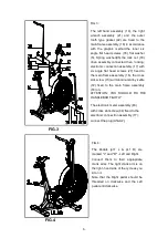
FIG.3
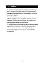
FIG.4
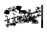
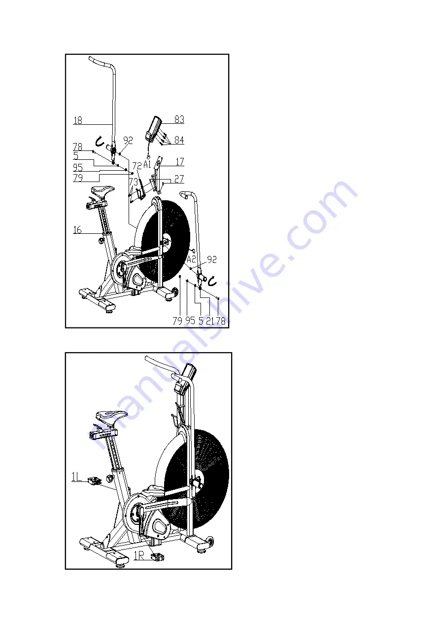
FIG.3:
The left hand assembly (18), the right
wrench assembly (21) and the outer
tooth type gasket (92) are fixed to the
main frame assembly (16) in accordance
with the graphic method,the inner six
angle flat head screws (78), flat washer
(5), Spring washer(95),the lock nut (79)
drive assembly connected then, locking;
electronic connection assembly (17) with
six angle flat head screws (27) fixed to
the main frame assembly (16), the cross
slot screw (73) will Aluminum Alloy kettle
(72) fixed to the main frame assembly
(16) on,
ATTENTION: YOU SHOULD FIX THE
HANDLEBAR TIGHTLY
The electronic meter assembly (83)
with cross slot screw (84) fixed to the
electronic connection assembly (17),
connect the plug (A1&A2),
FIG.4:
The Pedals (pt.1 L & pt.1 R) are
marked "L" and "R" - Left and Right.
Connect them to their appropriate
crank arms. The right crank arm is on
the right- hand side of the cycle as you
sit on it.
Note that the Right pedal should be
threaded on clockwise and the Left
pedal anticlockwise.
6


