SECTION 512-730-450
APPARATUS
623P4
Jack
Assy
Line
•
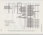
TABLE Dt
2660A1M TELEPHONE SET EQUIPPED WITH M1 A OR M1 B RINGER
MODIFICATION FOR 4A SPEAKERPHONE (NOTE
3)
WIRE OR LEAD
INDIVIDUA L
RING PARTY
LEAD
OR BRIDGED
(NOTE 1)
DESIG
COLOR
(NOTE
1)
R
(R)
L2
T
(G)
G
A1-SG
(Y)
L1
A
(BK)
*
(BR)
*
TIP PARTY
WITHOUT
I DENT.
(NOTE 1,4)
Switch
(S)
Connect to (O·W) adapter cord lead
Dial
(G)
G
Ringer
(G)
TBI-7 to G
Strap
R1
(BL·W)
L2
A1
(W-BR)
L1
M16C or M16H
AG
(W·O)
*
Adapter
T1
(W·BL)
Connect to (0) dial lead
t
Cord
I R
(G·W)
Connect to
(V)
dial lead
t
(Note 2, 3)
IT
(W·G)
*
LK
(O-W)
Connect to (S) line switch lead
t
Strap Between
(G)
A to L1
Net. Term
Note 1.
Terminals on network unless otherwise noted.
Note 2.
Insulate and store unused leads in adapter cord.
Note 3.
If housing must be notched to accommodate the adapter cord, refer to Section 503·100·100
for notching information.
Note 4.
4A speakerphone system is not designed for tip party identification service.
*
Insulate and store.
t
Use D-161488 connector.
Page 6
BSP 512-730-450-i05_1979-09-06.jpg Scanned by Frank Harrell, (Cowboy Frank) Castle Rock, Colorado Feb 23,2012 22:22:21


