background image

BELL  SYSTEM  PRACTICES 
AT 

TCo  Standard 

SECTION  5 12-730-450 

Issue  5,  September  1979 

660A 1,  2660A 1,  AND  2660A 1M  TELEPHONE  SETS 

CONNECTIONS 

SPEAKERPHONE  SYSTEM-4A 

1. 

GENERAL 

1.01 

Refer  to  Section  512-700-100  for  detailed 

information  on  components  of  the  4A 

speakerphone  system. 

1.02 

This  section  is  reissued  to: 

• 

Add  information  to  identify  registered  and 

typical  grandfathered  arrangements 

• 

Add  safety  information  for  the  85B1  power 

unit 

• 

Delete  4A  speakerphone  and  key  telephone 

system  wiring  figures  for  660A1,  2660A1, 
and  2660A1M  telephone  sets 

• 

Delete  key  telephone  system  modifications 
in  Tables  A  through  D. 

1.03 

This  section  provides  information  necessary 

to 

modify  and  connect  the  660A1  (MD), 

2660A1  (MD),  and  2660A1M  telephone set to  provide 
speakerphone  service  (Fig.  1  and  2). 

1.04 

Rotary  dial  telephone  sets  equipped  with  an 

8RA  dial  must  be equipped with  an 8CA  dial 

when  used  with  4A  speakerphone.  The  second  set 
of  off-normal  contacts  on  8CA  dial  shall  connect  to 
same  set  terminals  as  P3  and  P4  leads  from 

speakerphone. 

1.05 

The D6AF  or  D4BT  mounting  cord  furnished 

with  660A1  or  2660A1  sets  must  be  replaced 

by  a  D10R  mounting  cord  (ordered  separately).  In 
addition  the  telephone  set  must  be  modified  per 
Tables  A,  B,  or  C. 

1.06 

The  housing  on  earlier  versions  of  the 
2660A1M  telephone  set  must  be  notched  to 

accommodate the M16C  (MD) or M16H  adapter cord. 

Refer to Section 503-100-100 for notching information. 

In  addition  the  telephone  set  must  be  modified  per 
Table  D. 

2. 

CONNECTIONS 

A.  223-Type  Adapter 

2.01 

Cords  from  the  108-type  loudspeaker  set, 

680-type  transmitter,  and  85B1  power  unit 

are  installed  in  proper  receptacle  of  the  223A  (MD) 
or  223D  adapter. 

The  cover  must  be  fastened 

securely  to  assure  proper  mating  of  connectors. 

B. 

108-Type  Loudspeaker  Set 

2.02 

Loudspeaker  set  and  transmitter  must  be 
placed  a  minimum  of  one  foot  apart. 

C.  680-Type  Transmitter 

2.03 

Transmitter  must  be  at  least  two  feet  from 
the  transformer  or  any  ac  powered  device. 

D.  85B 1  Power  Unit 

2.04 

Power  shall  be  supplied  by connecting  power 
unit  as  shown  in  Fig.  3  through  6. 

2.05 

Use  an  ac  power  outlet  (not  under  control 

of  a  switch)  located  as  close  as  possible  to 

the  system  being  installed.  A  retaining  clamp will 
be  shipped with power unit  and  should be  mounted 
to  the  ac  receptacle  to  hold  power  unit  securely 
to  prevent  accidental  loss  of  power  (Fig.  1  and  2). 

Caution: 

Never  attempt  to  use  the 

same  power  supply  for  the  card  dialer 
and  the 

4A 

speakerphone  system. 

2.06 

The  power  unit  should  be  located  less  than 
125  feet  from  108-type  loudspeaker  set  when 

NOTICE 

Not  for  use  or  disclosure  outside  the 

Bell  System  except  under  written  agreement 

Printed  in  U.S.A. 

BSP S12-730-450-i05_1979-09-0l.jpg  Scanned by Frank Harrell, (Cowboy Frank) Castle  Rock, Colorado  Feb 23,2012  22:21:03 

Page  1 

Содержание 2660A1

Страница 1: ...hone set must be notched to accommodate the M16C MD or M16H adapter cord Refer to Section503 100 100 for notching information In addition the telephone set must be modified per Table D 2 CONNECTIONS A 223 Type Adapter 2 01 Cords from the 108 type loudspeaker set 680 type transmitter and 85B1 power unit are installed in proper receptacle of the 223A MD or 223D adapter The cover must be fastened sec...

Страница 2: ...l power unit when partially withdrawn from outlet Do not use Page 2 retaining clamp on outlets where cover mounting screw holds the duplex outlet in the box Warning Care should be taken to trim and dress leads connecting to low voltage output terminals of 85Bl power unit to assure that inadvertent connection to conducting surfaces or other power source does not occur If more than one power unit is...

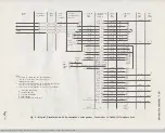
Страница 3: ... F of Net P2 of TB1 L1 of Net L1 of Net G to to L1 of TB1 F of Net R BL W TBI L1 T W BL F A1 O W TBI P2 T1 W 0 41 type dial terminal 6 P4 G W 41 type dial terminal 1 P3 W G 41 type dial terminal 2 A AG BR W LK W BR TBI L2 P1 S W 41 type dial terminal P1 P2 W S 41 type dial terminal P2 Note Replace BRA dial with BCA dial order separately Note 2 Replace D6AF mounting cord with D10R mounting cord ord...

Страница 4: ...R BL W TBI L1 T W BL F A1 O W TBI P2 D10R T1 W 0 41 type dial terminal 6 Mounting P4 G W 41 type dial terminal 1 Cord P3 W G 41 type dial terminal 2 Note 2 A AG BR W LK W BR TBI L2 P1 S W 41 type dial terminal P1 P2 W S 41 type dial terminal P2 Note 1 Replace BRA dial with SCA dial order separately Note 2 Replace D6AF mounting cord with D10R mounting cord order separately Note 3 Terminals on netwo...

Страница 5: ... DlOR A AG W 0 Mounting Tl W G Connect to 0 dial lead t Cord IR BR W Connect to V dial lead t Note 2 3 IT W BR LK S W Connect to S line switch lead t Note 1 Terminals on network unless otherwise noted Note 2 Replace D6AF mounting cord with DlOR mounting cord order separately Note 3 Insulate and store G W and W S mounting cord leads Note 4 4A speakerphone system is not designed for tip party identi...

Страница 6: ...W BL Connect to 0 dial lead t Cord IR G W Connect to V dial lead t Note 2 3 IT W G LK O W Connect to S line switch lead t Strap Between G A to L1 Net Term Note 1 Terminals on network unless otherwise noted Note 2 Insulate and store unused leads in adapter cord Note 3 If housing must be notched to accommodate the adapter cord refer to Section 503 100 100 for notching information Note 4 4A speakerph...

Страница 7: ...PE LOUDSPEAKER SET Fig 1 Typical Grandfathered 4A Speakerphone System Arrangement 660A 1 MD or 2660A1 MD Telephone Sets Using 223A MD or 223D Adapte Page 7 BSP 512 730 450 i05_1979 09 07 jpg Scanned by Frank Harrell Cowboy Frank Castle Rock Colorado Feb 23 2012 22 22 37 ...

Страница 8: ... TYPE LOUDSPEAKER SET Fig 2 Registered or Typical Grondfothered 4A Speakerphone System Arrangement 2660A 1M Telephone Set Using 223A MD or 2230 Adopter Page 8 BSP 512 730 450 i05_1979 Q9 08 jpg Scanned by Frank Harrell Cowboy Frank Castle Rock Colorado Feb 23 2012 22 22 54 ...

Страница 9: ...23A ADAPTER INSULATED AND STORED T NETWORK TERMINAL TERMINAL ON 41 TY PE DIAL DEAO DRESSED f STRAP APPEARS ON 108AA ONLY TO 85BI POWER UNIT I BK I YI M2FG CORD NOTE I Mt6C OR MI6H CORD BL W W 0 W BR W BL G Il W G o w R BL BL R w s S 11 R G BR WI O R I H iii t 1 i i 5 t lliJ li I l i t OO I J 223A OR 223D ADAPTER NOTE 2 C a 49 47 50 45 48 46 22 19 c317 e s c 26 e 4 3 27 e 42 28 e I _ _ R 0 ___ _ Fi...

Страница 10: ...D IS OEAO DRESSED IN PLUG Of 223A ADAPTER II INSULATED ANO STORED t NETWORK TERMINAL 0 161488 CONNECTORS OEAO DRESSED 11 STRAP APPEARS ON IOBAA ONLY 44A MI6C CONN OR BLK MI6H CORD 2 I Bl W 5 W 0 4 W BR n 7 W BL 9 G W 10 W G 3 o w II R BL lt II BL R lt W 5 BK I y I MZFG CORD NOTE I lt R 0 wl I i l fit A f b 1 A 22 OR AO N G NT ri 0 I II G W TVL I W G IGRD 4 Fig 4 Typical Grandfathered 4A Speakerpho...

Страница 11: ...R W BL G W W G O W R BL BL R W S S W R G G R 22lA OR ADAPTER NOTE l C 18 9 47 50 45 4B 46 22 19 2 20 22 0 j 24 25 10 5 BR W D R 21 c 7 c 16 44 4 26 4 4 27 42 4 28 41 29 _ c R 0 D2DN MTG CORD O W BL W W 0 W BR W BL G W W G R BL BL R W S S W R G G R BR W BR R R BR R 0 R S S R O R 10B TYPE LSPK SET VOL R1 11 AG 1 A1 n T1 15 P4 IR 10 Pl IT l 6 B1 K5B 1B R R1 K4B 20 B B1 K5C 19 R R1 K4C 14 AC 27 AC _2B...

Страница 12: ... FOR IA1 OR IA2 KTS USE REFER TO TABlE 0 INSULATED AND STORED t NETWORK TERMINAL D 161488 CONNECTORS I DEAD DRESSED lO R I R 0 TVL 7 0 GRD 5 0 ON 21 0 6 c l2 Fig 6 Registered 4A Speakerphone System Arrangement Connection to 2660A 1M Telephone Set BSP 512 730 450 i05_1979 09 12 Jpg Scanned by Frank Harrell Cowboy Frank Castle Rock Colorado Feb 23 2012 22 24 03 LK l l 5 z Ul L Ul ...

Отзывы: