background image

47

Heatless Desiccant Dryers

 | 

Instruction Manual


Section 11:

 Spares Information

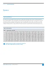
Purge Plug Identification 

Each dryer is set with the appropriate purge plug for the operating pressure specified at point of order. The purge plug fitted on 
the unit will be identified on the purge plug label, located underneath the rating plate on the right. If the inlet pressure to the dryer 
is adjusted to operate at an alternative working pressure other than initially specified, please contact the manufacturer and order 
an appropriate purge plug (identified in the table below). Before operating at the new working pressure this purge plug must be 
installed into the dryer. Failure to comply with these instructions could result in component failure and affect any warranty claims.

Appropriate purge plug selection is very important for function of the 
dryer. Failure to comply with this may affect your warranty.

Purge Plug Identification

Model

Operating Pressure psig (barg)

58 (4)

72.5 (5)

87 (6)

101.5 (7)

116 (8)

130.5 (9)

145 (10)

159.5 (11)

174 (12)

188.5 (13)

203 (14)

217.5 (15)

232 (16)

ACC 4

PPK008 PPK008 PPK007 PPK007 PPK006.5 PPK006.5 PPK006

PPK006

PPK006

PPK006

PPK005

PPK005

PPK005

ACC 6

PPK011 PPK010 PPK009 PPK008 PPK007.5 PPK007.5 PPK007.5 PPK007

PPK007

PPK007 PPK006.5 PPK006.5 PPK006.5

ACC 8

PPK012 PPK011 PPK010 PPK010 PPK009 PPK008 PPK008 PPK007.5 PPK007.5 PPK007.5 PPK007 PPK007 PPK007

ACC 10

PPK013 PPK012 PPK011 PPK011 PPK010 PPK009 PPK009 PPK009 PPK008.5 PPK008.5 PPK008.5 PPK008 PPK008

ACC 15

PPK015 PPK014 PPK013 PPK013 PPK012 PPK011 PPK011 PPK010 PPK010 PPK010 PPK009 PPK009 PPK009

ACC 25

PPK02.1 PPK01.9 PPK01.8 PPK01.7 PPK01.6 PPK01.5 PPK01.4 PPK013 PPK013 PPK012 PPK012 PPK012 PPK012

ACC 35

PPK028 PPK023 PPK021 PPK020 PPK018 PPK018 PPK016 PPK015 PPK015 PPK014 PPK014 PPK014 PPK014

Spares

Содержание Drypoint ACC 10

Страница 1: ...EN Instruction Technical Manual 4 35 BEKO TECHNOLOGIES CORP 900 Great SW Parkway Atlanta Georgia 30336 USA 1 800 235 6797 Phone 1 404 629 6666 Fax beko bekousa com www bekousa com ...

Страница 2: ...e complete the following information at the time of installation found on the rating label on the upper right hand side of dryer Model Number Serial Number Regulated Inlet Pressure Filtration present with Dryer Outlet Flow of Dryer Compressor Outlet Flow Supply Voltage When contacting the manufacturer regarding this product please have the above stated information at hand to speed up your query ...

Страница 3: ...Mechanical Installation 9 4 Electrical Installation 15 5 Operation 18 Start Up 18 Shut Down 19 6 Maintenance 25 Servicing 25 Purge Plug 28 Exhaust 29 Replacing Shuttle Valves 31 7 Energy Management 32 8 Troubleshooting 38 9 Technical Data 42 10 Component Parts 44 11 Spares Information 47 12 Warranty 49 Contents ...

Страница 4: ...ical disconnection plus isolation from the compressed air supply and full depressurization Only trained and competent persons familiar with the electrical requirements of the unit as laid out in this manual and electrical safety rules and regulations should be allowed to carry out work on the electrical components and power supply to the unit When carrying out any work on the unit use only correct...

Страница 5: ...lity for their own Health and Safety and the Health and Safety of others around them If you feel there is a significant risk you must take steps to either remove the risk altogether or reduce the risk prior to carrying out the activity If you need further support or guidance with this please consult your line manager or the HR Department There are safe systems of work and correct procedures in rel...

Страница 6: ... desiccant towers While one chamber is on stream removing water vapor the other is being carefully depressurized in preparation for regeneration The desiccant bed is regenerated by expanding a small amount of dry process air or purge air through the saturated desiccant Purge air passes to atmosphere through the silencer which is fitted to an exhaust valve The chamber is then repressurized with the...

Страница 7: ...e unit The package contains the following items refer to figure 2 1 Figure 2 1 Package contents INSTRUCTION MANUAL TUBING CLEARPOINT FILTER DIN PLUG BEKOMAT OPTIONAL M M UNION CERTIFICATE OF CONFORMITY CONNECTION KIT OPTIONAL 04 1705 001 01 Ra 6 7 8 9 6 7 8 9 6 7 8 9 6 7 8 9 6 7 8 9 6 7 8 9 6 7 8 9 6 7 8 9 6 7 8 9 DRYPOINT ACC DRYER Section 2 General Description ...

Страница 8: ...om valve assembly 4 Dryer base 5 Bottom valve fixing bolt 6 Front panel 7 Front panel fixing screw 8 Pressure housing 9 Pressure housing retaining bolt 10 Desiccant cartridge comes with dust filter 11 Multiport manifold 12 Top cover 13 Top cover fixing screw 14 Rear panel 15 Banjo fixing bolt 16 Pressure seal 17 Exhaust silencer 18 Purge plug 19 Purge plug fixing screw 20 Pre filter 21 Power cord ...

Страница 9: ...ndensate is drained into an oil water separator Fit any further filtration or ancillary equipment Drain kits supplied with dryer and comprise of the following Swivel elbow adapter and 5 32 4mm tubing It is recommended that a bypass line including filter is installed as per figure 3 13 1 2 Figure 3 1 Connecting pre filter Mechanical Installation Section 3 Mechanical Installation 1 Inlet 2 Outlet Fi...

Страница 10: ...ant Dryers Instruction Manual Orientation The dryers are designed to operate in both vertical and horizontal orientation Figure 3 3 Horizontal orientation Figure 3 4 Vertical orientation Section 3 Mechanical Installation ...

Страница 11: ...y be removed and rotated 180 to provide additional inlet outlet port positions Figure 3 6 A B C D E F Section 3 Mechanical Installation Tools required 4mm hex key 5mm hex key Directional arrows are etched into the inlet manifold Any all of the three outlet ports can be used on occasion Please ensure combined flow at outlet should not exceed specification Please adhere to regional regulations It is...

Страница 12: ...less Desiccant Dryers Instruction Manual Section 3 Mechanical Installation Figure 3 7 Level ground Figure 3 8 Drainage all tubing should be secured up to the point of drain to prevent whipping during discharge ...

Страница 13: ...x 122O F 50O C Max 122O F 50O C Max 122O F 50O C Max 122O F 50O C Figure 3 10 Hard piped installation Max 122O F 50O C Max 122O F 50O C Figure 3 11 Exposure to heat Max 122O F 50O C Max 122O F 50O C Max 122O F 50O C Max 122O F 50O C Figure 3 9 Location Section 3 Mechanical Installation ...

Страница 14: ...cal Installation A B C D Figure 3 13 Typical installation Figure 3 12 Direction of flow To prevent back flow into the dryer a non return valve should be placed in line downstream of the dryer This is essential when more than one dryer is used in a single application ...

Страница 15: ...et as shown in figure 4 3 and 4 4 The dryer controller is double insulated therefore no earth is required on the power connector External fuse to be connected to plug The cable selection must suit local installation regulations and be appropriate to power consumption as shown in the Power Supply table Power Supply Supply Amp 12 VDC 0 80 24 VDC 0 40 100 VAC 0 16 115 VAC 0 14 230 VAC 0 07 240 VAC 0 ...

Страница 16: ...1 PIN 3 5 VDC 2 3 Volt Free 1 PIN 12 24VDC INPUT INPUT 1 2 3 1 2 3 1 2 3 AC POWER SUPPLY Open Connection From Factory 2 3 24VDC Not used Earth 1 PIN INPUT 24VDC 1 2 3 DC POWER SUPPLY Blanked off From Factory ENERGY MANAGEMENT ALARM Drain Solenoid Valve Right Tower Solenoid Valve Controller Rear Controller Front Left Tower Solenoid Valve Figure 4 2 Wiring diagram Blanking Cap DIN Connector Gasket A...

Страница 17: ...ient over voltage IEC 60664 Class II Pollution degree 2 IEC 60664 A circuit breaker or switch must be installed near the dryer This should be easy to reach and shall be certified according to EN60947 1 and EN60947 3 The switch or circuit breaker shall be marked as the disconnecting device for the dryer and needs to be marked with on and off positions Output connections do not provide isolation fro...

Страница 18: ...then operates in regeneration mode The main air flow and drying function is then transferred to the desiccant cartridge that was previously under regeneration The cycle of operation continues in this pattern with the cartridges switching alternately between drying and regenerating Start up procedure 4 SCFM 35 SCFM See figure 5 1 and 5 2 Close valves A B C and D Switch on compressor Open valve A sl...

Страница 19: ...to controller Shut down Procedure Close valve B Close valve A Leave dryer running for 15 minutes to fully depressurize Switch off all electrical power to the dryer Under no circumstances must compressed air be allowed to flow through the dryer following switch off of electrical power This will result in terminal failure of the desiccant cartridges and regeneration will not be possible When Illumin...

Страница 20: ...with the internal air pressure of the dryer allowing the small spring on the outside of the diaphragm to press the diaphragm against its seat keeping air from exiting the silencer Note Any air flowing through the dryer passes through both towers Figure 5 3 Initial Pressurization Power Off 1 0 µ Pre Filter Water Separator Right S V Left S V 0 01 µ After Filter To Bottom Valve Alternate Inlet Altern...

Страница 21: ...ide of the diaphragm to vent through the solenoid valve to atmosphere As air pressure on the outside of the diaphragm drops the diaphragm is pushed away from the valve seat by the internal air pressure of the dryer and air rushes out the silencer as the left tower depressur izes The shuttle valves move to the lower pressure left side and seal off against the main process flow Once the tower pressu...

Страница 22: ...alve Seconds 0 120 170 290 340 2 Seconds At completion of Stage 1 the left solenoid valve is de energized Air pressure on the outside of the right diaphragm increases as air flows through the tiny bleed hole in the diaphragm The air pressure on the outside of the diaphragm quickly equalizes with the internal air pressure of the dryer allowing the small spring on the outside of the diaphragm to pre...

Страница 23: ...de of the diaphragm to vent through the solenoid valve to atmosphere As air pressure on the outside of the diaphragm drops the diaphragm is pushed away from the valve seat by the internal air pressure of the dryer and air rushes out the silencer as the left tower depressuriz es The shuttle valves move to the lower pressure right side and seal off against the main process flow Once the tower pressu...

Страница 24: ...alve Seconds 0 120 170 290 340 2 Seconds At completion of Stage 3 the left solenoid valve is de energized Air pressure on the outside of the left diaphragm increases as air flows through the tiny bleed hole in the diaphragm The air pressure on the outside of the diaphragm quickly equalizes with the internal air pressure of the dryer allowing the small spring on the outside of the diaphragm to pres...

Страница 25: ...ure shutdown and start up procedures are followed prior to carrying out any maintenance work on the dryer The manufacturer will not accept responsibility for physical injury damage or delays caused by failure to observe the instructions in this manual and manuals provided with your equipment Please refer to Section 11 Spares Information Figure 6 2 Models 4 SCFM 35 SCFM with front panel removed Ser...

Страница 26: ...Ensure O ring seals are in place when installing cartridge and assembly in pressure housing 10 Follow above steps in reverse to finish installing new cartridge into the dryer 11 Repeat steps 1 10 for the second pressure housing 12 Ensure the dryer is leak free before operating pressure is applied to the dryer 13 Follow start up procedure as stated on page 18 of this manual 14 Continue to page 27 t...

Страница 27: ...he blue pad on the front display of the dryer panel for 5 seconds During the five second period the power indicator will flash green When the reset has been successful indicator X will flash green once to confirm that it has been completed successfully Sweep the reset disc on the blue pad if the LEDs do not flash as stated Please note If Energy Management is activated their will be a 6 hour delay ...

Страница 28: ... ensure ease of fit Appropriate purge plug selection is very important for function of the dryer Failure to comply with this may affect your warranty 1 Securing screw 2 Purge plug Tools required Pozidrive screwdriver Figure 6 12 4 SCFM 35 SCFM Purge plug changeout stage 2 Important information Ensure shutdown and start up procedures are followed prior to carrying out any maintenance work on the dr...

Страница 29: ...nd remove Replace with new silencer Ensure spacers are placed between silencer and valve block Tools required Not required Important information Ensure shutdown and start up procedures are followed prior to carrying out any maintenance work on the dryer The manufacturer will not accept responsibility for physical injury damage or delays caused by failure to observe the instructions in this manual ...

Страница 30: ...FM Top and bottom diaphragms Important information Ensure shutdown and start up procedures are followed prior to carrying out any maintenance work on the dryer The manufacturer will not accept responsibility for physical injury damage or delays caused by failure to observe the instructions in this manual and manuals provided with your equipment Important information Ensure that correct new diaphra...

Страница 31: ... Remove shuttle Replace shuttle Reinsert shuttle seat Re secure tower Tools required 5mm hex key Figure 6 23 4 SCFM 35 SCFM Filter and tower removal Figure 6 24 4 SCFM 35 SCFM Shuttle seat and shuttle removal Bottom Shuttle Valve Location Top Shuttle Valve Location Important information Bottom shuttle removal shown Same process used for top shuttle removal and installation ...

Страница 32: ...implest of arrangements a manual switch may be employed to shut the purge off when the air downstream of the dryer is not being used Commonly used on point of use systems For example if the dryer is only used to supply air of an appropriate dryness to a specific machine or application the dryer will only be required when the machine is in use and may be shut off either manually or possibly via ext...

Страница 33: ...psig in the example the purge shuts off until the pressure switch deactuates at 95 psig in example The point at which the switch deactuates may be adjusted to suit the system If it is determined that the dew point drops to an unacceptable level the deactuation point must be increased Please note that with most standard pressure switches the dead band is fixed such that the activation and deactuati...

Страница 34: ... of the devices mentioned as they might be connected for use in controlling a dryer s purge function Please note that specific details differ between device manufacturers so in all cases the manufacturer s specifications should be adhered to Section 7 Energy Management Figure 7 4 Using an Electronic Pressure Switch for Purge Control DRYER CONTROLLER RELAY Normally Closed open to turn purge off PIN...

Страница 35: ...s should be taken into consideration to ensure that the air flow remains sufficiently dry It is extremely important to understand that the purge may only be shut off during periods of low or no demand This feature if used otherwise can result in permanent damage to the desiccant beds resulting in loss of drying capacity and possibly mechanical failure The cartridges must not be allowed to become f...

Страница 36: ... and discard Slip cable end through DIN connector s cable gland and out through the front of the DIN connector Strip the outer insulation of the cable back approx 3 4 20mm Strip the conductor insulation back approx 1 8 3mm If possible using a meter check the continuity between the two wires to ensure that the switch is in a closed position If it is possible to verify the switch function as well th...

Страница 37: ...rought into the controller via the rear panel with a grommet An external power source is required 1 Connect the switching pole of an externally powered alarm device to terminals 1 and 2 of alarm DIN connector 2 With the power removed from the dryer and the alarm lead wired as described in 1 above remove the cover from the DIN connection marked Alarm and connect the wired DIN connector ensuring the...

Страница 38: ...maximum specified Low inlet pressure Check against specification High inlet temperature Check against specification Silencer blocked or damaged Replace silencer Air leaks Tighten joints or fit new seals Desiccant life exceeded Replace desiccant cartridges Desiccant contaminated Check inlet filter and drains replace cartridges EM is active when air is flowing through dryer Check EM wiring logic and...

Страница 39: ...uit Flashing red P1 Z LED Replace solenoid valve Controller fault Flashing red P2 POWER LED Replace controller Tube connections from filter into dryer and from filter to drain reversed None Reverse tubes Troubleshooting Energy Management Problem Possible Cause Action Dryer does not enter Energy Management when switching device is activated and or Dryer does not enter Energy Management when EM cont...

Страница 40: ...Manual LED Controller Display Status LED Signal Description Power off Left hand tower purge cycle Repressurization cycle Right hand tower purge cycle Repressurization including drain Service warning every 11 500 hours Section 8 Troubleshooting ...

Страница 41: ...Instruction Manual LED Controller Display Status LED Signal Description Service due every 12 000 hours Right hand solenoid fault Left hand solenoid fault Drain valve fault Controller fault Low power fault Section 8 Troubleshooting ...

Страница 42: ...ons please contact the manufacturer Reference Conditions Measurement Performance Effective inlet pressure 101 5 psig 7 barg Effective inlet temperature 95 F 35 C Relative humidity of air at inlet 95 Pressure dewpoint standard version 40 F 40 C Specified Limitation for Operation Measurement Performance Maximum inlet air pressure 232 psig 16 barg Minimum inlet air pressure 58 psig 4 barg Maximum amb...

Страница 43: ...1 89 1064 11 06 281 3 6 92 52 9 24 0 ACC 35 3 8 35 59 simplex 57 44 1459 11 06 281 3 6 92 68 4 31 0 Pressure Correction Factor PCF Operating Pressure psig 58 73 87 102 116 131 145 160 174 189 203 218 232 barg 4 5 6 7 8 9 10 11 12 13 14 15 16 PCF 0 62 0 75 0 87 1 00 1 12 1 25 1 37 1 50 1 62 1 75 1 87 2 00 2 12 Always use the pressure correction factor PCF closest to actual inlet pressure condition ...

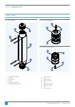
Страница 44: ...nit 3 Bottom valve assembly 4 Dryer base 5 Bottom valve fixing bolt 6 Front panel 7 Front panel fixing screw 8 Pressure housing 9 Pressure housing retaining bolt 10 Desiccant cartridge comes with dust filter 11 Multiport manifold 12 Top cover 13 Top cover fixing screw 14 Rear panel 15 Banjo fixing bolt 16 Pressure seal 17 Exhaust silencer 18 Purge plug 19 Purge plug fixing screw 20 Pre filter 21 P...

Страница 45: ...s 1 4 9 2 5 8 6 7 3 2 Fig 10 3 Bottom block assembly 1 Top Block 2 Shuttle seat 3 Shuttle 4 Purge Plug 5 Top diaphragm large hole with disc 6 Compression spring 7 Top bonnet 1 Bottom block 2 Shuttle seat 3 Shuttle 4 Silencer 5 Bottom diaphragm small hole with disc 6 Compression spring 7 Bottom bonnet 8 4mm straight adaptor 9 Spacers ...

Страница 46: ...mbly 2 3 5 4 6 1 8 9 10 7 Fig 10 6 Bottom tower plug assembly 13 12 11 15 14 1 Top tower plug assembly 2 Cartridge 3 Extrusion bolt 4 Extrusion 5 Extrusion corner bracket 6 Bottom tower plug assembly 7 Tower plug screw 8 Seal 9 Top tower plug 10 Top banjo adapter 11 Nut 12 Bottom banjo adapter 13 Bottom tower plug 14 Seal 15 Tower plug screw ...

Страница 47: ...lection is very important for function of the dryer Failure to comply with this may affect your warranty Purge Plug Identification Model Operating Pressure psig barg 58 4 72 5 5 87 6 101 5 7 116 8 130 5 9 145 10 159 5 11 174 12 188 5 13 203 14 217 5 15 232 16 ACC 4 PPK008 PPK008 PPK007 PPK007 PPK006 5 PPK006 5 PPK006 PPK006 PPK006 PPK006 PPK005 PPK005 PPK005 ACC 6 PPK011 PPK010 PPK009 PPK008 PPK00...

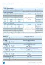
Страница 48: ...its plus a complete valve service kit and service manual Every 24 000 Hours or 4 Years ACC 6 4048844 4023706 Every 24 000 Hours or 4 Years ACC 8 4048845 4023707 Every 24 000 Hours or 4 Years ACC 10 4048846 4023708 Every 24 000 Hours or 4 Years ACC 15 4048847 4023709 Every 24 000 Hours or 4 Years ACC 25 4048848 4023710 Every 24 000 Hours or 4 Years ACC 35 4048849 4023711 Every 24 000 Hours or 4 Yea...

Страница 49: ...r Improper completion of repairs Use of non original or non approved parts for service or maintenance Important Note Industrial Compressed Air Desiccant Dryers The desiccant dryer range is designed for warrantied and intended for use in fixed industrial compressed air applications only Use on non fixed installations such as marine e g offshore shipboard transportable e g portable air treatment uni...

Страница 50: ...S CORP 900 Great SW Parkway Atlanta Georgia 30336 USA 1 800 235 6797 Phone 1 404 629 6666 Fax beko bekousa com www bekousa com BEKO reserves the right to make changes and improvements to the product and or this manual without prior notice ...

Отзывы: