21
Heatless Desiccant Dryers
|
Instruction Manual
Section 5:
Operation
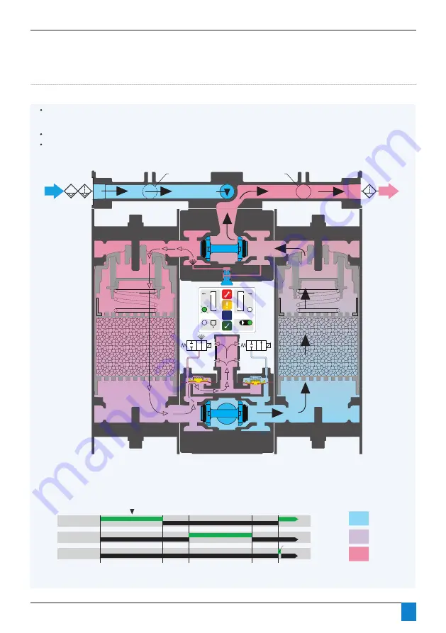
Figure 5.4: Stage 1: Left Tower Purging, Right Tower Drying
1.0 µ
Pre-Filter
Water
Separator
Right
S.V.
Left
S.V.
0.01 µ
After Filter
To Bottom Valve
Alternate Inlet
Alternate Outlet
TIMING CHART:
ON
OFF
ON
Wet
Purge
Dry
OFF
SV 2
(Right Solenoid Control Valve)
LEGEND:
SV 1
(Left Solenoid Control Valve)
ON
OFF
DV 1
(Prefilter Drain Solenoid Valve)
Seconds: 0
120
170
290
340
2 Seconds
The left solenoid is energized allowing air on the outside of the diaphragm to vent through the solenoid valve to atmosphere. As air pressure on the outside of the
diaphragm drops, the diaphragm is pushed away from the valve seat by the internal air pressure of the dryer and air rushes out the silencer as the left tower depressur-
izes.
The shuttle valves move to the lower pressure (left) side and seal off against the main process flow.
Once the tower pressure drops, dry, purge air passes from the outlet of the right tower into the top of the left tower via the purge orifice. The air then flows down through
the left desiccant bed evacuating the trapped moisture and venting it to atmosphere.
Figure 5.4: Stage 1: Left Tower Purging, Right Tower Drying
IN
OUT


