


11
6.2
Indicator function:
FunC
This configuration function defines the relationship
between the indicator’s 4/20mA input current and
the indicator’s display. Three alternatives are
available:
5td
Standard linear relationship
root
Square root extraction
Lin
16 segment adjustable lineariser
To reveal the existing indicator function select
FunC
from the configuration menu and press
(
. If the
function is set as required, press
)
to return to
the menu, or press the
&
or
*
button to change
the setting, followed by the
)
button to return to
the configuration menu.
5td
Linear
Provides a linear relationship between
the 4/20mA indicator input current and
the indicator display.
root
Square root extraction
Primarily intended to linearise the square
law 4/20mA output from differential
flowmeters.
For reference, the following table shows
the output current from a non-linearised
differential flowmeter.
% of full flow
Current output mA
2.5
4.01
10.0
4.16
25.0
5.00
50.0
8.00
75.0
13.00
100.0
20.00
When the root function is selected the
indicator will display flow in linear units.
Lin
16 segment adjustable lineariser
Enables non-linear variables to be
displayed by the indicator in linear
engineering units. Use of the lineariser is
described in section 7 of this instruction
manual.
6.3
Resolution:
rE5n
This function defines the resolution of the least
significant display digit. Decreasing the display
resolution can improve the readability of a noisy
signal. Select
rE5n
from the menu and press
(
which will reveal the current display resolution.
To change the resolution press the
&
or
*
button to select
1
,
2
,
5
or
10
digits, followed by the
)
button to enter the selection and return to the
configuration menu.
6.4
Position of the decimal point:
dP
A dummy decimal point can be positioned between
any of the digits or it may be absent. To position
the decimal point select
dP
from the menu and
press
(
. The decimal point can be moved by
pressing the
&
or
*
push button. If a decimal
point is not required it should be positioned beyond
the most or least significant digit. When
positioned as required press the
)
button to enter
the selection and return to the configuration menu.
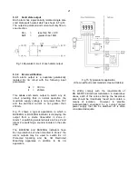
6.5
Calibration using an external
current source:
CAL
This function enables the zero and span of the
indicator to be adjusted using an external
calibrated current source. When used with an
accurate traceable current source this is the
preferred method of calibration.
Zero is the indicator display with 4mA input
Span is the indicator display with 20mA input
To calibrate the indicator select
CAL
from the
configuration menu and press
(
. The indicator
will display
2Ero
which is a request for a 4mA input
current. Adjust the external current calibrator to
4.000mA and again press
(
which will reveal the
current zero display. The flashing digit of the
indicator display can be changed by pressing the
&
or
*
buttons, when set as required pressing
(
will transfer control to the next digit. When all
the digits have been adjusted, press
)
to enter
the new zero and return to the
2Ero
prompt .
Pressing the
*
button will cause the indicator to
display
5PAn
which is a request for a 20mA input
current. Adjust the external current calibrator to
20.000mA and again press
(
which will reveal
the existing span display. The flashing digit of the
indicator display can be changed by pressing the
&
or
*
buttons, when set s required pressing
(
will transfer control to the next digit. When all the
digits have been adjusted press
)
to enter the
new span and return to the
5PAn
prompt. Finally
press
)
again to return to the configuration menu.
Notes:
a. The indicator input current must be adjusted to
the required value before the zero and span
functions are entered by pressing the
(
button.
b. Indicators may be calibrated at currents other
than 4 and 20mA, withiin the range 3.8 to
21.0mA providing the difference between the
two currents is greater than 4mA. If these
conditions are not complied with, the indicator
displays
FaiL
and aborts the calibration.
c. If the zero current is greater than the span
current the instrument will be reverse acting i.e.
an increasing input current will cause the
display to decrease.
Содержание BA304NG
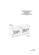
Страница 1: ...Issue 4 1st November 2017 BA304NG BA324NG Ex nA Ex tc loop powered field mounting indicators Issue 4...
Страница 10: ...10...
Страница 15: ...15...
Страница 23: ...23...


