background image

5

ULTRALINK ULM2000

Registering your purchase and equipment with us helps us process your repair claims quicker and more
efficiently.

Thank you for your cooperation!
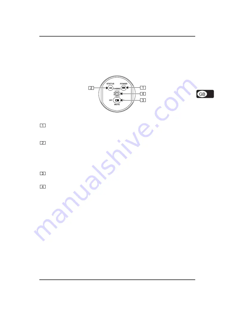
2. CONTROL ELEMENTS

In this chapter, different control elements of your ULM2000 will be described, explained in detail, and
you will get useful information on how to use them.

Fig. 2.1: ULM2000

’s underside

POWER
To power the hand-held transmitter on or off, keep the POWER button pressed for at least 2 seconds.
Briefly pressing the POWER button confirms your choices when entering values (refers to later chapters).
Additionally, you can check the current transmitter settings (selected channel and battery condition).

STATUS LED
Through repeated blinking, the status LED gives the account of the current settings for all parameters.
We differentiate between 3 different blinking tempos:

V

The LED blinks slowly when you, for example, successfully leave the programming mode.

V

To give the account of the channel number or individual frequency values, the LED blinks with
medium tempo.

V

Rapid blinking indicates an error, for example an empty battery or a faulty entry.

MUTE switch
Engaging the MUTE  switch mutes the microphone. Additionally, the ULM2000 can be switched to
programming mode by selecting the digits 9 or 0; or, you can get a readout of a specific unit setting.

SELECTION SWITCH
Using a screwdriver, you can select different values on the SELECTION SWITCH. For example, you
can select a channel number and the frequency.

The SERIAL NUMBER is located on the transmitter battery compartment. To get to the serial number, please
open the battery compartment (see ch. 1.1.3).

3. HAND-HELD TRANSMITTER OPERATION

A brief overview with the graphic representation on operating the transmitter is found on the last page of this
user manual (QUICK REFERENCE GUIDE).

3.1 Turning the microphone on

1.

Press the POWER button located at the bottom of the microphone and keep it pressed for 2 seconds.

2.

A blink code follows, indicating the battery condition:
1 = Battery is nearly empty     . . .

5 = Battery is fully charged

3.

Afterward, a second blink code indicates to which channel the transmitter is currently set.
1 = channel 1 is selected    . . .

8 = channel 8 is selected

3. HAND-HELD TRANSMITTER OPERATION

Содержание ULTRALINK ULM2000

Страница 1: ...User s manual Version 1 1 August 2006 ULTRALINK ULM2000 ...

Страница 2: ...portant operating and maintenance instructions in the accompanying literature Please read the manual DETAILED SAFETY INSTRUCTIONS 1 Read these instructions 2 Keep these instructions 3 Heed all warnings 4 Follow all instructions 5 Do not use this apparatus near water 6 Clean only with dry cloth 7 Do not install near any heat sources such as radiators heat registers stoves or other apparatus includi...

Страница 3: ...ULR2000 from BEHRINGER comprises a modern high performance wireless transmission system Thanks to its amazing set of features you can use the ULM2000 in all situations in which the highest sound quality and mobility are a must e g live concerts events and video productions Depending on your local wireless transmission regulations you can use up to 20 systems simultaneously The IRC compander system...

Страница 4: ... course using only one 9V battery decreases the effective uptime When using only one battery it does not matter which of the two battery compartments you use Either one will work When running the unit on two batteries please make sure that both batteries are equally fresh Therefore whenever changing batteries always use two brand new batteries When the battery is nearly depleted the LED located on...

Страница 5: ... blinks with medium tempo V Rapid blinking indicates an error for example an empty battery or a faulty entry MUTE switch Engaging the MUTE switch mutes the microphone Additionally the ULM2000 can be switched to programming mode by selecting the digits 9 or 0 or you can get a readout of a specific unit setting SELECTION SWITCH Using a screwdriver you can select different values on the SELECTION SWI...

Страница 6: ...hed to the programming mode 2 Turn the selection switch to 9 and confirm your selection by keeping the POWER button pressed for about 2 seconds The LED indicates confirmation by blinking once with medium tempo and blinking once slowly The transmitter is now in the programming mode and awaits the entry of a 6 digit frequency 3 Enter all 6 digits one after another in the following fashion V Select t...

Страница 7: ...to different frequencies This way you can always select a frequency range that assures the best signal transmission The following table shows which frequencies are stored in the factory presets CHANNEL PRESET 2 PRESET 3 PRESET 4 1 798 700 MHz 798 400 MHz 798 100 MHz 2 799 950 MHz 798 950 MHz 798 650 MHz 3 800 650 MHz 799 800 MHz 799 500 MHz 4 801 050 MHz 801 450 MHz 801 150 MHz 5 802 850 MHz 803 2...

Страница 8: ...sed for 2 seconds As a confirmation the LED blinks slowly once and then once again with medium tempo The transmitter is now in the programming mode and waits for you to enter a one digit number 3 Select one of the following two digits on the selection switch V Low Gain select 5 V High Gain select 6 If a valid selection is made the LED blinks quickly once to confirm your selection This way you can ...

Страница 9: ...ection is made the LED blinks quickly once to confirm your selection This way you can be sure that a correct value is entered in regard to preset MicGain and Auto Mute selection even before confirming your selection Selecting the values 1 through 4 changes the preset settings ch 3 4 Selecting 5 or 6 changes the Mic Gain settings ch 3 5 Values 9 and 0 are invalid 4 Confirm your selection by briefly...

Страница 10: ...ne another by brief pauses The value 0 is signaled by a very short blink of the LED and you will easily tell a 0 from a 1 If the receiver is not powered on no status is indicated Briefly pressing the POWER button will neither turn the transmitter on nor off 4 3 Preset 1 Make sure that the microphone is not set to mute MUTE switch is set to OFF 2 Turn the selection switch to 1 2 3 or 4 and confirm ...

Страница 11: ...desired basic sound has been achieved should you start to use equalizers and signal processors if any at all remember less is often more 6 APPLICATION EXAMPLE Fig 6 1 shows how easy it is to use the ULM2000 Simply connect the receiver ULR2000 to your mixing console Fig 6 1 Wiring the ULR2000 receiver and the ULM2000 microphone 7 INSTALLATION 7 1 Installation information V Always make sure that the...

Страница 12: ...ULR2000 receiver under optimal environmental conditions AF characteristics coupled to ULR2000 Noise reduction high performance IRC compander system Pre Deemphase RF system AF frequency response 30 19000 Hz 3dB THD at nom deviation and 1kHzNF 0 4 SNR at peak deviation 105 dB A Microphone Type Panasonic back electret condenser with FET impendance converter Pickup pattern Unidirectional cardioid Sens...

Страница 13: ...arks by BEHRINGER nor affiliation of the trademark owners with BEHRINGER BEHRINGER accepts no liability for any loss which may be suffered by any person who relies either wholly or in part upon any description photograph or statement contained herein Colors and specification may vary slightly from product Products are sold through our authorised dealers only Distributors and dealers are not agents...

Страница 14: ...14 ULTRALINK ULM2000 MICROPHONE QUICK START GUIDE MICROPHONE QUICK START GUIDE ...

Отзывы: