Beef Eater 7000 Series Скачать руководство пользователя страница 37

37

ASSEMBLING THE BARBECUE

25

24

25

26

26

23

22

1

2

 The hole is at the back

Attach 4 castors

Castor with 
locks at the front 
position

Castor with 
locks at the front 
position

M6 x 12mm

x 16

Содержание 7000 Series

Страница 1: ...Assembly and Operating Instructions FOR OUTDOOR USE ONLY 7000 SERIES BMF7645SA BMF7655SA BMG7642SA BMG7652SA AUSTRALIA NEW ZEALAND ...

Страница 2: ...rectly and that you read the safety instructions carefully to avoid misuse and hazards We recommend that you keep this instruction booklet for future reference and pass it on to any future owners After unpacking the appliance please check it is not damaged If in doubt do not use the appliance but contact your local customer care centre This appliance complies with requirements of Australian Standa...

Страница 3: ...dismantle or adjust the control valves Do not attempt to dismantle or adjust the regulator Do not test for leaks with a naked flame Do not modify the construction of this appliance or modify the injector orifice size Do not place articles on or against this appliance Do not obstruct any ventilation of the barbecue Do not allow children to operate or play near the barbecue Failure to adhere to the ...

Страница 4: ...ey top panel x1 13 Trolley frame coross x1 14 Rubber cover x2 15 Trolley right panel assy x1 16 Right reinforcing plate x1 17 Trolley mid panel assy x1 18 Transformer x1 19 Trolley left panel assy x1 20 Front door assy x1 21 Door hinge x2 22 Door handle assy x1 23 Drawers assy x2 24 Gas cylinder holder slider assy x1 25 Trolley bottom panel x1 26 Castors x2 27 Castor with lock x2 3 6 1 2 4 5 7 12 ...

Страница 5: ...5 BMF7645SA PRODUCT DIMENSIONS DIMENSIONS 1602 708 1284 ...

Страница 6: ...ey top panel x1 13 Trolley frame cross x 1 14 Rubber cover x2 15 Trolley right panel assy x1 16 Right reinforcing plate x1 17 Trolley mid panel assy x1 18 Transformer x1 19 Trolley left panel assy x1 20 Door assy x1 21 Door Hinge x2 22 Door handle assy x1 23 Drawer assy x 2 24 Gas cylinder hold slider assy x 1 25 Trolley bottom panel assy x1 26 Casters x2 27 Castors with lock x2 3 6 1 2 4 5 7 12 1...

Страница 7: ...7 BMF7655SA PRODUCT DIMENSIONS DIMENSIONS 1758 708 1284 ...

Страница 8: ...x1 12 Trolley top panel x1 13 Trolley frame coross x1 14 Rubber cover x2 15 Trolley right panel assy x1 16 Door fixing stator x1 17 Trolley middle frame x1 18 Trolley left panel assy x1 19 Front left door assy x1 20 Front right door assy x2 21 Door handle assy x2 22 Door magnet x1 23 Door magnet stator x1 24 Trolley bottom panel x1 25 Castors x2 26 Castor with lock x2 BMG7642SA 3 6 1 2 4 5 7 12 13...

Страница 9: ...9 BMG7642SA PRODUCT DIMENSIONS DIMENSIONS 1602 685 1284 ...

Страница 10: ... x1 12 Trolley top panel x1 13 Trolley frame coross x1 14 Rubber cover x2 15 Trolley right panel assy x1 16 Door fixing stator x1 17 Trolley middle frame x1 18 Trolley left panel assy x1 19 Front left door assy x1 20 Front right door assy x2 21 Door handle assy x2 22 Door magnet x1 23 Door magnet stator x1 24 Trolley bottom panel x1 25 Castors x2 26 Castor with lock x2 BMG7652SA 3 6 1 2 4 5 7 12 1...

Страница 11: ...11 BMG7652SA PRODUCT DIMENSIONS DIMENSIONS 1758 685 1284 ...

Страница 12: ...r side burner BMF7645SA BMF7655SA 2 4 1 35 Injector diameter rear burner BMF7645SA BMF7655SA 1 55 0 94 GAS TYPE Gas type Model Name Main Burner Qty Rating MJ h Rear Burner Qty Rating MJ h Side Burner Qty Rating MJ h Total Rating MJ h NG BMG7642SA 4 68 0 0 1 17 85 BMG7652SA 5 85 0 0 1 17 105 BMF7645SA 4 68 1 11 1 21 100 BMF7655SA 5 85 1 11 1 21 117 LPG BMG7642SA 4 68 0 0 1 17 85 BMG7652SA 5 85 0 0 ...

Страница 13: ...UE BMF7645SA BMF7655SA BMF7645SA BMF7655SA ASSEMBLY For BMF7645SA BMF7655SA M6 x 12mm M4 x 10mm flat head M4 x 10mm countersunk head x4 x15 x60 Tools required Hexagonal screwdriver Phillips screwdriver Wrench 22mm Wrench 19mm ...

Страница 14: ...14 ASSEMBLING THE BARBECUE 25 26 26 27 27 24 1 2 Castor with locks at the front position The hole is at the back BMF7645SA BMF7655SA ASSEMBLY M6 x 12mm x 16 Attach 4 castors ...

Страница 15: ...15 ASSEMBLING THE BARBECUE 4 18 19 3 ...

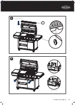
Страница 16: ...16 19 15 ASSEMBLING THE BARBECUE 5 6 11 BMF7645SA BMF7655SA ASSEMBLY ...

Страница 17: ...17 ASSEMBLING THE BARBECUE 7 8 11 ...

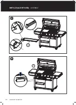
Страница 18: ...18 ASSEMBLING THE BARBECUE 17 9 10 BMF7645SA BMF7655SA ASSEMBLY ...

Страница 19: ...19 ASSEMBLING THE BARBECUE 11 12 13 16 ...

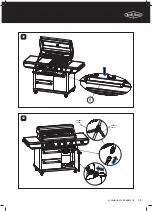
Страница 20: ...20 ASSEMBLING THE BARBECUE 11 13 14 23 BMF7645SA BMF7655SA ASSEMBLY ...

Страница 21: ...21 ASSEMBLING THE BARBECUE 15 16 20 22 21 ...

Страница 22: ...e screw in clockwise for 1 2 complete turns Then press the button Pull the the upper and lower two tabs out of the rectangular slot Finally pull the hooks out When connected the upper and lower two tabs should be aligned with the rectangular slot Then press down when hear pop the assembly is in place Firstly insert the upper and lower hook into the slots BMF7645SA BMF7655SA ASSEMBLY ...

Страница 23: ...23 ASSEMBLING THE BARBECUE 19 20 14 5 Spanner 19mm Spanner 19mm Electrical wires need to be kept outside through the indicated hole ...

Страница 24: ...transformer wires and the lighting wires screw the connection to seal BMF7645SA BMF7655SA ASSEMBLY Recommend at least 2 people to lift Due to the assembled body being a heavy lift Carefully locate the gas pipe into the hole of the trolley top panel ...

Страница 25: ...25 ASSEMBLING THE BARBECUE 23 24 Insert the wires into the trolley to hide the wires Disassemble the hose to easily access the screw hole ...

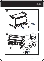
Страница 26: ...26 ASSEMBLING THE BARBECUE 25 26 BMF7645SA BMF7655SA ASSEMBLY ...

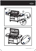
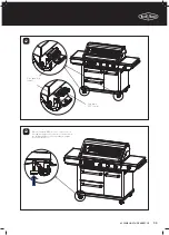
Страница 27: ...27 ASSEMBLING THE BARBECUE 27 28 6 7 ...

Страница 28: ...28 ASSEMBLING THE BARBECUE 29 30 BMF7645SA BMF7655SA ASSEMBLY ...

Страница 29: ...29 ASSEMBLING THE BARBECUE 31 32 Assemble side burner gas pipe to the manifold using 2 spanners Connect the wires underneath the side burner ...

Страница 30: ...30 ASSEMBLING THE BARBECUE 4 33 34 3 2 Locate the flame tamers 2 flame tamers for 4 burners 3 flame tamers for 5 burners Drainage holes are at the front BMF7645SA BMF7655SA ASSEMBLY ...

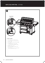
Страница 31: ...31 ASSEMBLING THE BARBECUE 35 36 1 Locate the warming rack Sliding locked Sliding unlocked ...

Страница 32: ...32 ASSEMBLING THE BARBECUE 10 37 38 9 BMF7645SA BMF7655SA ASSEMBLY ...

Страница 33: ...33 ASSEMBLING THE BARBECUE 39 40 8 Spanner 19mm Spanner 22mm ...

Страница 34: ... soap After connection of the hose turn on the gas supply at the gas bottle Using a brush apply the solution to all gas connection points and look for bubbles forming Bubbling will indicate a leak Turn off the gas supply and re tighten the joint Repeat the leak test If the leak persists turn off the gas at the bottle and contact a licensed gas fitter to correct BMF7645SA BMF7655SA ASSEMBLY ...

Страница 35: ...UE 42 43 Push down ON to brake Push down OFF to move When moving the BBQ it is necessary to raise the leveling foot and at the same time it cannot touch the fixed plate above so as to avoid affecting the rotation of the wheels ...

Страница 36: ...CUE BMG7642SA BMG7625SA BMG7642SA BMG7652SA ASSEMBLY For BMG7642SA BMG7652SA M6 x 12mm M4 x 10mm flat head M4 x 10mm countersunk head x4 x2 x55 Tools required Hexagonal screwdriver Phillips screwdriver Wrench 22mm Wrench 19mm ...

Страница 37: ...37 ASSEMBLING THE BARBECUE 25 24 25 26 26 23 22 1 2 The hole is at the back Attach 4 castors Castor with locks at the front position Castor with locks at the front position M6 x 12mm x 16 ...

Страница 38: ...BARBECUE 3 4 15 18 Assemble M6 head screw x6 three on each side on the trolley bottom panel do not fully tighten Assemble left and the right side panels into the keyholes then tighten screws BMG7642SA BMG7652SA ASSEMBLY ...

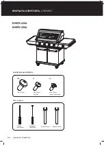
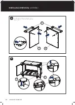
Страница 39: ...39 ASSEMBLING THE BARBECUE 5 Assemble the back trolley panels with M6 head screws x7 11 11 ...

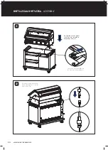
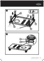
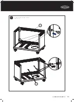
Страница 40: ...40 ASSEMBLING THE BARBECUE 6 7 13 13 BMG7642SA BMG7652SA ASSEMBLY ...

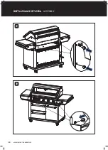
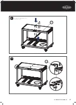
Страница 41: ...41 ASSEMBLING THE BARBECUE 17 16 8 9 Assemble the trolley top panel with M6 head screws x8 ...

Страница 42: ...42 ASSEMBLING THE BARBECUE 10 11 20 19 21 21 19 Assemble the door handle assy remove the screws from the handle then assemble the handle to door and fix with screws BMG7642SA BMG7652SA ASSEMBLY ...

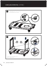
Страница 43: ...43 ASSEMBLING THE BARBECUE 14 12 13 ...

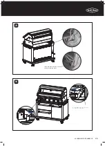
Страница 44: ...44 ASSEMBLING THE BARBECUE 14 15 BMG7642SA BMG7652SA ASSEMBLY ...

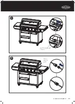
Страница 45: ...45 ASSEMBLING THE BARBECUE 7 6 16 17 Align side burner gas pipe through the hole pull wire through the hole ...

Страница 46: ...46 ASSEMBLING THE BARBECUE 18 19 BMG7642SA BMG7652SA ASSEMBLY ...

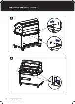
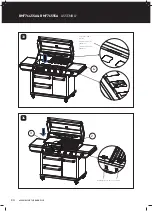
Страница 47: ...47 ASSEMBLING THE BARBECUE 4 20 21 ...

Страница 48: ...48 ASSEMBLING THE BARBECUE 22 23 2 3 1 Drip hole should be at front side BMG7642SA BMG7652SA ASSEMBLY ...

Страница 49: ...49 ASSEMBLING THE BARBECUE 10 24 25 ...

Страница 50: ...50 ASSEMBLING THE BARBECUE 26 27 9 8 Put on the foil box holder onto the drip tray Put the foil oil tray into the holder BMG7642SA BMG7652SA ASSEMBLY ...

Страница 51: ...51 ASSEMBLING THE BARBECUE 28 29 Push down ON to brake Push down OFF to move ...

Страница 52: ...HE BARBECUE 30 BMG7642SA BMG7652SA ASSEMBLY When moving the BBQ it is necessary to raise the leveling foot and at the same time it cannot touch the fixed plate above so as to avoid affecting the rotation of the wheels ...

Страница 53: ...53 NATURAL GAS INSTALLATION NATURAL GAS INSTALLATION 1 2 Take out the warming rack cooking plate and cooking grill Disassemble the R latch ...

Страница 54: ...54 NATURAL GAS INSTALLATION NATURAL GAS INSTALLATION 3 4 Take out the burners Change the injector size for the NG Version ...

Страница 55: ...55 NATURAL GAS INSTALLATION 5 6 Unscrew the 6 M4 head screws from the rear burner cover Take out the front baffle plate and the rear burner cover ...

Страница 56: ...56 NATURAL GAS INSTALLATION 7 8 Change the injector size Unscrew the M5 head screws x2 from the side table NATURAL GAS INSTALLATION ...

Страница 57: ...57 NATURAL GAS INSTALLATION 9 10 Disassemble the side burner and change the injector for the NG version ...

Страница 58: ...RAL GAS INSTALLATION Mobile restraint with hose assembly When the mobile barbecue is connected to a fixed gas supply via a flexible hose connection a retaining tether of adequate strength shall be fixed to the appliance and be suitable to be fixed to the wall within 50mm of each connection point The retaining tether must be less than 80 of the gas hose length ...

Страница 59: ...nd level and no overhead cover Within a partial enclosure that includes an overhead cover and no more than two walls The barbecue may be within a partial enclosure that includes an overhead cover and more than two walls the following shall apply At least 25 of the total wall area is completely open and At least 30 of the remaining wall area is open and unrestricted In the case of balconies at leas...

Страница 60: ...NTENTS RAIN BAFFLE INSTALLATION 1 2 Remove the hood screw M4 x 10mm flat head screw 4 PCS Rain baffle Assemble the rain baffle M4 x 10mm flat head screw 4 PCS BMG7642SA and BMG7652SA BMG7642SA and BMG7652SA ...

Страница 61: ...NTENTS 1 2 Remove the hood screw M4 x 10mm flat head screw 4 PCS Rain baffle Assemble the rain baffle M4 x 10mm flat head screw 4 PCS BMG7645SA and BMG7655SA BMG7645SA and BMG7655SA RAIN BAFFLE INSTALLATION ...

Страница 62: ...with the cooking surfaces covered 2 Read the instructions before lighting 3 To light burner depress knob and rotate to HIGH 4 Keep knob pushed in for 5 seconds to ensure flame safety is activated if fitted 5 If burner did not light turn knob to the OFF position Allow gas to disperse then repeat lighting procedure Using cookware on the side burner Do not use oversized cookware or place cookware off...

Страница 63: ... supply line to the barbecue inlet located on the right side of the appliance using either hard plumbing or a flexible hose connected to a bayonet point also known as a quick connect fitting Refer to AS 5601 or your local installation code for pipe sizing details Secure all joints spanner wrench tight but do not over tighten Test gas pressure by removing the last burner from the left hand side of ...

Страница 64: ...n Be careful not to block the orifice at the end of valve where the gas injector is fitted and do not remove any of the thread sealing compound from the orifice where the injector is located 7 Check the identification mark stamped on Hex Head of the injector to confirm that it is the correct size NG 2 10mm Screw correct Jet back into place 8 When fitting the NG gas injectors to the end of the jet ...

Страница 65: ...eaks The gas leak testing procedure should be conducted every time a gas cylinder is refilled and reconnected to the appliance or after any new gas connection is made In a small container mix up a solution of water and detergent or soap Mix the solution well For LPG propane make sure that the gas supply valve on the gas cylinder is turned on For Natural Gas make sure that the gas shutoff valve is ...

Страница 66: ...urner 1 Push in and hold the control knob down while turning slowly in an anti clockwise direction until the starter mechanism engages at the two o clock position At this time the gas will start to flow 2 Hold the control knob in while continuing to turn the knob toward the High or twelve o clock position 3 The starter mechanism will click and the main burner will now light Continue turning the kn...

Страница 67: ... about 10 minutes after you have finished cooking This helps to burn away any excess food residues and oil and makes cleaning easier 1 Be sure to turn off all control knobs and the cylinder valve for LPG propane or shut off valve for Natural Gas 2 Allow barbecue to cool 3 Clean the drip tray and cooking surfaces 4 Clean any food spills from the side burner 5 Lower the hood and side burner lid Remo...

Страница 68: ... the manufacturer FREQUENCY SERVICE AND MAINTENANCE EACH USE EVERY SIX MONTHS BY AUTHORISED SERVICE PERSON EVERY 2 YEARS Check all hoses for cracks and leaks Check that all gas connections are tight Clean entire barbecue thoroughly Check and tighten all bolts on barbecue and cart Clean and inspect vaporizers and reflectors Clean and inspect barbecue burners Clean and inspect gas injectors and cont...

Страница 69: ...ments AS5601 ventilation requirements for 9kg cylinder storage are Where of sheet metal or similar impervious construction there shall be ventilation openings at the top and bottom of the enclosure or recess each opening providing a free area of at least 200cm2 for every cylinder enclosed For LPG installations having enclosed cabinetry below the separation panel that does not contain a gas bottle ...

Страница 70: ...heat the barbecue prior to cooking This barbecue is fitted with high power burners In most conditions it will only be necessary to preheat the barbecue for 5 minutes before cooking can commence As with most things experience will familiarise you with the time required to achieve the desired cooking temperature If the unit does not operate correctly refer to troubleshooting section Cooking methods ...

Страница 71: ...ide burners to medium Five burner Three inside burners off One outside burner to high Other outside burner to medium TYPE OF MEAT COOKING TEMPERATURE APPROXIMATE COOKING TIMES Beef 180 C 355 F 45 55min per kg 20 25min per lb Lamb 180 C 355 F 45 55min per kg 20 25min per lb Pork 170 C 340 F 55 60min per kg 25 30min per lb Veal 160 C 320 F 40 50min per kg 18 23min per lb Poultry 180 C 355 F 40 50min...

Страница 72: ...ecue warranty Cleaning the control panel and hood Wash the surfaces of the control panel and hood with a soft sponge and a solution of hot water and a mild dishwashing liquid Do not use highly caustic harsh or abrasive chemical cleaners or scouring pads as these will damage the surface of the panels Cleaning the hood glass Baked on fat on the inside of the hood glass can be removed by using a razo...

Страница 73: ...tioned in the barbecue frame Burner ports or throat blocked Check that the burner ports are not blocked by spider webs or insect nests Clean out as required Barbecue lights but goes out soon after starting Fuel supply turned off Turn on gas valve at cylinder Gas cylinder low or empty Replace cylinder and carry out a leak check Kink in gas hose Check that the gas line is not kinked or twisted Wind ...

Страница 74: ...74 NOTES NOTES NOTES ...

Страница 75: ... Appliances not supplied by Electrolux J JVZTL PJ KHTHNL OPJO KVLZ UV HќLJ OL VWLYH PVU VM OL Appliance d damage to the Appliance caused by i negligence or accident ii misuse or abuse including failure to properly maintain or service iii improper negligent or faulty servicing or repair works done by anyone other than an Electrolux authorised repairer or ASC iv normal wear and tear v power surges e...

Страница 76: ... 51 004 762 341 B_MAN_7000_MOB_Apr22 Contact us if you need more help AUSTRALIA phone 1300 307 939 email customercare beefeaterbbq com web beefeaterbbq com NEW ZEALAND phone 0800 436 245 email customercare electrolux co nz web beefeaterbbq com ...

Отзывы: