Access from the user program
KL8001 and KL9060
28
Version: 2.0.0
5
Access from the user program
5.1
Process image
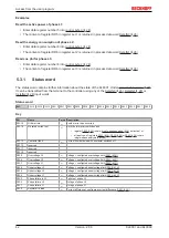
The power terminal is represented in the process image with 12 bytes of input and output data each. These
are organized as follows:
Byte-Offset
without
Word-Alignment*
Byte-Offset
with
Word-Alignment*
Format
Input data
Output data
0
0
Byte
)
1
2
Word
DataIN0
DataOUT0
3
4
Byte
)
4
6
Word
DataIN1
DataOUT1
6
8
Byte
)
7
10
Word
DataIN2
DataOUT2
9
12
Byte
10
14
Word
not used**
not used**
*) Word-Alignment: The Bus Coupler places values on even byte addresses
**) The process image is extended by an unused word in the input and output range, so that the power
terminal appears like a four-channel analog terminal.
5.1.1
Control and Status Bytes
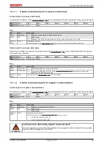
The control bytes 0 (CB0), 1 (CB1) and 2 (CB2) are in the
controller to the power terminal. Pay attention to the
of the control bytes to the process
input data words in process data mode.
The status bytes 0 (SB0), 1 (SB1) and 2 (SB2) are in the
and are transferred from the
power terminal to the controller.
Since the structure and application of the control and status bytes are identical, they are described below
using control byte 0 (CB0) and status byte 0 (SB0) as examples.
Содержание KL8001
Страница 2: ......
Страница 4: ...Table of contents KL8001 and KL9060 4 Version 2 0 0...

