background image

Access from the user program

KL31x2

43

Version: 2.4.0

Key

Bit

Name

Description

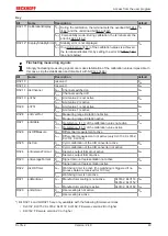
SB1.7 RegAccess

0

bin

Acknowledgment for process data mode

SB1.6 Error

0

bin

no error detected

1

bin

KL3142 up to firmware 2B

• Overload (bit 

SB1.1 [

}

 42]

 is

set) or

• Underload (bit 

SB1.0 [

}

 42]

 is

set)

KL3142 with firmware 2C or higher
and 

R32.14 [

}

 49]

 = 1

bin

KL3132, KL3152, KL3162, KL3172,
KL3182 up to firmware 2A

KL3132, KL3152, KL3162, KL3172,
KL3182 with firmware 2B or higher
and 

R32.14 [

}

 49]

 = 1

bin

KL3142 with firmware 2C or higher

• The last calibration was

terminated with an error (no
stability)

KL3132, KL3152, KL3162, KL3172,
KL3182 with firmware 2B or higher

SB1.5,
SB1.4

StateThreshold2 00

bin

Limit value 2 [

}

 50]

 is not enabled via bit 

R32.10 [

}

 49]

 of the feature

register

01

bin

Process data is less than limit value 2

10

bin

Process data is greater than limit value 2

11

bin

Process data equals limit value 2

SB1.3,
SB1.2

StateThreshold1 00

bin

Limit value 1 [

}

 50]

 is not enabled via bit 

R32.9 [

}

 49]

 of the feature

register

01

bin

Process data is less than limit value 1

10

bin

Process data is greater than limit value 1

11

bin

Process data equals limit value 1

SB1.1 Overload

1

bin

Process data is greater than specified in
register 

R21 [

}

 48]

. The red error LED

of this channel is lit.

The calibration is active if SB1.0
and SB1.1 are set
simultaneously.

SB1.0 Underload

1

bin

Process data are less than specified in
register 

R22 [

}

 48]

. The red error LED

of this channel is lit.

Register communication

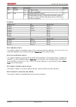
Control byte 1 (in register communication)

Control byte 1 (CB1) is located in the 

output image [

}

 39]

, and is transmitted from the controller to the

terminal.

Bit

CB1.7

CB1.6

CB1.5

CB1.4

CB1.3

CB1.2

CB1.1

CB1.0

Name

RegAccess R/W

Reg. no.

Key

Bit

Name

Description

CB1.7

RegAccess

1

bin

Register communication switched on

CB1.6

R/W

0

bin

Read access

1

bin

Write access

CB1.5 to CB1.0

Reg. no.

Register number:
Enter the number of the 

register [

}

 45]

 that you

- want to read with input data word 

DataIn [

}

 39]

 or

- want to write with output data word 

DataOut [

}

 39]

.

Содержание KL31 2 Series

Страница 1: ...Documentation KL31x2 Two Channel Accurate Analog Terminals 2 4 0 2019 02 11 Version Date...

Страница 2: ......

Страница 3: ...3 3 2 4 Pin assignment 24 3 3 ATEX Special conditions standard temperature range 26 3 4 ATEX Documentation 27 3 5 Application example for KL3172 0000 28 4 Configuration Software KS2000 29 4 1 KS2000 I...

Страница 4: ...Table of contents KL31x2 4 Version 2 4 0...

Страница 5: ...a diagrams and descriptions in this documentation Trademarks Beckhoff TwinCAT EtherCAT EtherCAT P Safety over EtherCAT TwinSAFE XFC and XTS are registered trademarks of and licensed by Beckhoff Automa...

Страница 6: ...ained specialists in control automation and drive engineering who are familiar with the applicable national standards Description of instructions In this documentation the following instructions are u...

Страница 7: ...n of terminal points 3 and 7 adapted to final pin assignment KL3132 KL3142 KL3152 KL3162 and KL3182 added 1 0 First version KL3172 only Firmware and hardware versions Documen tation Version KL3132 000...

Страница 8: ...4 0 WW week of production calendar week YY year of production FF firmware version HH hardware version Example with ser no 35 04 1B 01 35 week of production 35 4 year of production 2004 1B firmware ver...

Страница 9: ...lated to the higher level automation device The input channels of one Bus Terminal have differential inputs and possess a common internal ground potential With their small measuring error of 0 05 of t...

Страница 10: ...tus byte Bit width in the output process image 2 data words 2 control byte Power supply for the electron ics via the K bus Current consumption from K bus typically 85 mA Electrical isolation 500 V dif...

Страница 11: ...orm to the higher level automation device The input channels of the Bus Terminals have differential inputs and possess a common internal ground potential With their small measuring error of 0 05 of th...

Страница 12: ...trol byte Power supply for the electronics via the K bus Current consumption from K bus typically 85 mA Surge voltage resistance 35 VDC Electrical isolation 500 V differential input K bus Connection s...

Страница 13: ...llows Input signal Value KL3142 0000 KL3152 0000 KL3162 0000 KL3172 0000 KL3172 0500 KL3172 1000 dec hex 0 mA 4 mA 0 V 0 V 0 V 0 V 0 0x0000 20 mA 20 mA 10 V 2 V 500 mV 1 V 65535 0xFFFF Input signal Va...

Страница 14: ...etting bit SB1 6 42 in the status byte and by switching off the associated RUN LED Calibration can be disabled by the controller via control byte CB1 1 42 if necessary If calibration is disabled over...

Страница 15: ...ertain tolerance range specified via register R48 51 This further increases the precision This function can be deactivated via bit R32 7 49 Limit values The terminal offers the option of monitoring tw...

Страница 16: ...Product overview KL31x2 16 Version 2 4 0 Fig 3 Differential measuring...

Страница 17: ...ff if LED Run 1 is not lit Run 2 green ON Channel 2 active process data contain valid analog value OFF Channel 2 not active Calibration is performed analog value in the process data not current frozen...

Страница 18: ...fieldbus coupler Join the compo nents with tongue and groove and push the terminals against the mounting rail until the lock clicks onto the mounting rail If the terminals are clipped onto the mounti...

Страница 19: ...ents The six spring contacts of the K Bus E Bus deal with the transfer of the data and the supply of the Bus Terminal electronics The power contacts deal with the supply for the field electronics and...

Страница 20: ...mm from the group of terminals WARNING Risk of electric shock The PE power contact must not be used for other potentials 3 2 Connection 3 2 1 Connection system WARNING Risk of electric shock and damag...

Страница 21: ...tes the risk of wires being mixed up The familiar dimensions of the terminal only had to be changed slightly The new connector adds about 3 mm The maximum height of the terminal remains unchanged A ta...

Страница 22: ...sassembly or wiring of the Bus Terminals Terminals for standard wiring ELxxxx KLxxxx and for pluggable wiring ESxxxx KSxxxx Fig 11 Connecting a cable on a terminal point Up to eight terminal points en...

Страница 23: ...uctors using the direct plug in technique i e after stripping the wire is simply plugged into the terminal point The cables are released as usual using the contact release with the aid of a screwdrive...

Страница 24: ...nt WARNING Risk of injury through electric shock and damage to the device Bring the Bus Terminals system into a safe de energized state before starting mounting disassembly or wiring of the Bus Termin...

Страница 25: ...hannel 2 GND 7 Internal ground internally connected to terminal point 3 Shield 8 PE contact internally connected to terminal point 4 NOTE Power contacts connected to the next terminal In hardware vers...

Страница 26: ...inst the rated operating voltage being exceeded by more than 40 due to short term interference voltages The individual terminals may only be unplugged or removed from the Bus Terminal system if the su...

Страница 27: ...Beckhoff terminal systems in potentially explosive ar eas ATEX Pay also attention to the continuative documentation Notes about operation of the Beckhoff terminal systems in potentially explosive are...

Страница 28: ...afe de energized state before starting mounting disassembly or wiring of the Bus Terminals Monitoring the cell voltages of a battery with several KL3172 Fig 14 KL3172 0000 application example NOTE Do...

Страница 29: ...s Box Modules can be prepared before the commissioning phase Later on this configuration can be transferred to the terminal station in the commissioning phase by means of a download For documentation...

Страница 30: ...es directly online The same high level dialogs and register access are available for this purpose as in the configuration phase The KS2000 offers access to the process images of the bus couplers and F...

Страница 31: ...In the example shown this is a Ethernet Coupler BK9000 a digital input terminal KL1xx2 a precise two channel analog input terminal for signals between 0 and 2 V KL3172 a bus end terminal KL9010 Fig 16...

Страница 32: ...hannel 1 of the KL3172 For the KL3172 the branches Register Settings and ProcData are displayed Register 33 enables direct access to the KL3172 registers A dialog mask for the parameterization of the...

Страница 33: ...tware KS2000 KL31x2 33 Version 2 4 0 4 3 Register You can access the registers of the KL3172 directly under Register The meaning of the register is explained in the register overview 45 Fig 18 Registe...

Страница 34: ...he other channel default not disabled Disabling of a channel is indicated by its Run and error LEDs going out User scaling active R32 0 49 You can activate user scaling here default deactivated Manufa...

Страница 35: ...ctivated Register values User offset R33 50 You can specify the user offset between 32768 and 32767 here default 0 User gain R34 50 You can specify the user gain between 0 and 65535 here default 256 c...

Страница 36: ...le applications of our products for certain areas of application The application notes provided here are based on typical features of our products and only serve as ex amples The notes contained in th...

Страница 37: ...coupler e g BK1120 or embedded PC KL3314 KL9010 Download https infosys beckhoff com content 1033 kl31x2 Resources zip 5996114571 zip Preparations for starting the sample programs tnzip file TwinCAT 3...

Страница 38: ...figuration of the example Checking NetId the EtherCAT tab of the EtherCAT device shows the configured NetId The first 4 numbers have to be identical with the project NetId of the target system The pro...

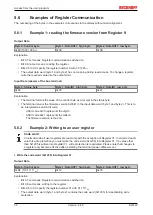
Страница 39: ...n Please refer to the Mapping 40 page for the allocation of the bytes and words to the addresses of the controller The meaning of the control and status bytes is explained in Control and status bytes...

Страница 40: ...he Bus Coupler conditions such as compact or full evaluation Intel or Motorola format word alignment switched on or off The Bus Couplers BKxxxx LCxxxx and Bus Terminal Controllers BCxxxx BXxxxx are su...

Страница 41: ...1 SB2 Ch1 D1 CB2 Ch1 D1 2 Ch2 D1 Ch2 D0 Ch2 D1 Ch2 D0 Complete evaluation in Motorola format Address Input data Output data Requirements Word offset High byte Low byte High byte Low byte Complete eva...

Страница 42: ...it has no function This byte is not assigned or used by the terminal module 5 3 Control and status byte Channel 1 Process data mode Control byte 1 for process data mode Control byte 1 CB1 is located...

Страница 43: ...ld1 00bin Limit value 1 50 is not enabled via bit R32 9 49 of the feature register 01bin Process data is less than limit value 1 10bin Process data is greater than limit value 1 11bin Process data equ...

Страница 44: ...ller Bit SB1 7 SB1 6 SB1 5 SB1 4 SB1 3 SB1 2 SB1 1 SB1 0 Name RegAccess R W Reg no Key Bit Name Description SB1 7 RegAccess 1bin Acknowledgment for register access SB1 6 R 0bin Read access SB1 5 to SB...

Страница 45: ...W RAM R16 47 Hardware version number e g 0x0000 e g 0dec R W SEEPROM R17 47 Vendor calibration Offset typically 0x0046 70dec R W SEEPROM R18 47 Vendor calibration Gain typically 0x5208 typically 2100...

Страница 46: ...served R63 reserved In multiples of 100 ms In multiples of register R40 51 5 5 Register description The registers are used for the parameterization of the Bus Terminals and are available for each chan...

Страница 47: ...132 0xC3C 3132dec KL3162 0xC5A 3162dec KL3142 0xC46 3142dec KL3152 0xC50 3152dec R9 Firmware version Register R9 contains the ASCII coding of the terminal s firmware version e g 0x3141 1A The 0x31 cor...

Страница 48: ...ned during the vendor calibration R24 Reference calibration value Gain This register contains the reference value of the calibration which is determined during the vendor calibration R31 Code word reg...

Страница 49: ...uring range limitation not active 1bin 1bin Measuring range limitation active R32 7 enStable 0bin Stabilization 15 of the calibration value not active 1bin 1bin Stabilization 15 of the calibration val...

Страница 50: ...it value can be activated in the feature register through bit R32 10 49 R37 Filter constants of the A D converter and configuration bits for the filter default value 35C0hex The terminal has two low p...

Страница 51: ...is register contains the calibration interval for the terminal s automatic calibration The unit is 100 ms The automatic calibration can be activated through bit R32 5 49 in the feature register R44 Fo...

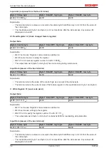
Страница 52: ...returns the firmware version 0x3341 in the input data word byte 1 and byte 2 This is to be interpreted as an ASCII code ASCII code 0x33 represents the digit 3 ASCII code 0x41 represents the letter A...

Страница 53: ...Byte 1 DataIN1 high byte Byte 2 DataIN1 low byte 0x9F 1001 1111bin 0x12 0x35 Explanation The terminal returns the value of the control byte as a receipt in the status byte The terminal returns the cu...

Страница 54: ...yte 0 Status byte Byte 1 DataIN1 high byte Byte 2 DataIN1 low byte 0xA0 1010 0000bin 0x00 0x02 Explanation The terminal returns the value of the control byte as a receipt in the status byte The termin...

Страница 55: ...components there Beckhoff Headquarters Beckhoff Automation GmbH Co KG Huelshorstweg 20 33415 Verl Germany Phone 49 0 5246 963 0 Fax 49 0 5246 963 198 e mail info beckhoff com Beckhoff Support Support...

Страница 56: ...nnecting a cable on a terminal point 22 Fig 12 KL3132 pin assignment 24 Fig 13 KL3142 pin assignment 24 Fig 14 KL3172 0000 application example 28 Fig 15 KS2000 configuration software 29 Fig 16 Display...

Отзывы: