Access from the user program
KL31x2
42
Version: 2.4.0
Key
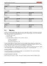
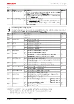
Complete evaluation: In addition to the process data, the control and status bytes are also mapped into the
address space.
Motorola format: Motorola or Intel format can be set.
Word alignment: In order for the channel address range to commence at a word boundary, empty bytes are
inserted into the process image as appropriate.
SB n: Status byte for channel n (appears in the input process image).
CB n: Control byte for channel n (appears in the output process image).
Ch n D0: channel n, lower-value data byte
Ch n D1: channel n, higher-value data byte
reserved: This byte is assigned to the process data memory, although it has no function.
"-": This byte is not assigned or used by the terminal/module.
5.3
Control and status byte
Channel 1
Process data mode
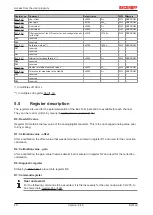
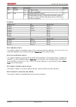
Control byte 1 (for process data mode)
Control byte 1 (CB1) is located in the
, and is transmitted from the controller to the
terminal.
Bit
CB1.7
CB1.6
CB1.5
CB1.4
CB1.3
CB1.2
CB1.1
CB1.0
Name
RegAccess -
-
-
-
-
CaliDisReq StartManC
ali
Key
Bit
Name
Description
CB1.7
RegAccess
0
bin
Register communication off (process data mode)
CB1.6 to CB1.2
-
0
bin
reserved
CB1.1
CaliDisReq
1
bin
Blocking automatic calibration
CB1.0
StartManCali
1
bin
start manual calibration
Status byte 1 (for process data mode)
The status byte 1 (SB1) is located in the
and is transmitted from terminal to the controller.
Bit
SB1.7
SB1.6
SB1.5
SB1.4
SB1.3
SB1.2
SB1.1
SB1.0
Name
RegAccess Error
StateThreshold2
StateThreshold1
Overload
Underload


