


Access from the user program
KL2692
26
Version: 2.0.0
5
Access from the user program
5.1
Process image
The KL2692 is represented in the process image with a minimum of 3 bytes of input data and 3 bytes of
output data. These are organized as follows:
Byte offset
(without word
alignment)
Byte offset
(with word align-
ment*)
Format
Input data
Output data
0
0
Byte
1
2
Word
DataIN
DataOUT
*) Word alignment: The Bus Coupler places values on even byte addresses
Key
SB: Status byte
CB: Control byte
DataIN: input word
DataOUT: output word
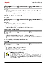
Note
No compact process image
The KL2692 cannot be operated with compact process image (without control and status
bytes), since control and status bytes are required for process data operation of the
KL2692 to function correctly. Even if your Bus Coupler is set to compact process image,
the KL2692 is represented with its complete process image!
5.2
Control and status byte
Process data mode
Control byte (for process data mode)
The control byte (CB) is located in the
, and is transmitted from the controller to the
terminal.
Bit
CB.7
CB.6
CB.5
CB.4
CB.3
CB.2
CB.1
CB.0
Name
RegAccess -
-
-
-
-
-
Toggle
Key
Bit
Name
Description
CB7
RegAccess
0
bin
Register communication off (process data mode)
CB.6 to CB.2
-
0
bin
reserved
CB.0
Toggle
Toggle bit
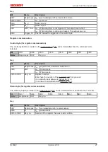
Status byte (for process data mode)
The status byte (SB) is located in the
, and is transmitted from terminal to the controller.
Bit
SB.7
SB.6
SB.5
SB.4
SB.3
SB.2
SB.1
SB.0
Name
RegAccess -
-
-
IN_2
IN_1
WDT_Run Toggle_St
Содержание KL2692
Страница 1: ...Documentation KL2692 Watchdog Terminal 2 0 0 2017 08 07 Version Date...
Страница 2: ......
Страница 4: ...Table of contents KL2692 4 Version 2 0 0...


