Beckhoff KL2692 Скачать руководство пользователя страница 1

Documentation

KL2692

Watchdog Terminal

2.0.0
2017-08-07

Version:
Date:

Содержание KL2692

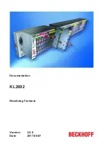
Страница 1: ...Documentation KL2692 Watchdog Terminal 2 0 0 2017 08 07 Version Date...

Страница 2: ......

Страница 3: ...ction system 14 3 2 2 Wiring 16 3 2 3 Connection 18 3 3 Application example 19 4 KS2000 Configuration Software 20 4 1 KS2000 Introduction 20 4 2 Parameterization with KS2000 21 4 3 Register 23 4 4 Set...

Страница 4: ...Table of contents KL2692 4 Version 2 0 0...

Страница 5: ...e data diagrams and descriptions in this documentation Trademarks Beckhoff TwinCAT EtherCAT Safety over EtherCAT TwinSAFE XFC and XTS are registered trademarks of and licensed by Beckhoff Automation G...

Страница 6: ...iliar with the applicable national standards Description of symbols In this documentation the following symbols are used with an accompanying safety instruction or note The safety instructions must be...

Страница 7: ...and hardware versions Documentation Version KL2531 Firmware Hardware 2 0 0 1C 04 1 0 1 1B 01 1 0 1B 00 0 2 00 0 1 00 The firmware and hardware versions delivery state can be taken from the serial num...

Страница 8: ...e or connector or by a fault in a bus device The cycle monitoring time can be parameterized The Bus Terminal has an enable input that enables the relay to be switched on if a correct toggle signal is...

Страница 9: ...rature range during operation 0 C 55 C Permissible ambient temperature range during storage 25 C 85 C Permissible relative air humidity 95 no condensation Dimensions W x H x D approx 15 mm x 100 mm x...

Страница 10: ...l on the bus stops toggling and remains in low state 6 The relays switch off after a missed toggle cycle Stop 7 Toggle signal on the bus starts to toggle again 8 Rising edge at input 1 9 Falling edge...

Страница 11: ...en On Relay contact 13 14 make contact 1 closed Relay 2 green On Relay contact 23 24 make contact 2 closed Watchdog OK green On The watchdog is triggered on a regular basis Error red not used not used...

Страница 12: ...ieldbus Coupler Join the compo nents with tongue and groove and push the terminals against the mounting rail until the lock clicks onto the mounting rail If the Terminals are clipped onto the mounting...

Страница 13: ...s The six spring contacts of the K Bus E Bus deal with the transfer of the data and the supply of the Bus Terminal electronics The power contacts deal with the supply for the field electronics and thu...

Страница 14: ...0 mm from the group of terminals WARNING Risk of electric shock The PE power contact must not be used for other potentials 3 2 Connection 3 2 1 Connection system WARNING Risk of electric shock and dam...

Страница 15: ...eliminates the risk of wires being mixed up The familiar dimensions of the terminal only had to be changed slightly The new connector adds about 3 mm The maximum height of the terminal remains unchan...

Страница 16: ...ion disassembly or wiring of the Bus Terminals Terminals for standard wiring ELxxxx KLxxxx and for pluggable wiring ESxxxx KSxxxx Fig 10 Connecting a cable on a terminal point Up to eight terminal poi...

Страница 17: ...HD Terminals are connected without tools for single wire conductors using the direct plug in technique i e after stripping the wire is simply plugged into the terminal point The cables are released as...

Страница 18: ...onnection for 13 1 Relay contact 13 NO contact 1 14 2 Relay contact 14 NO contact 2 24 V 3 24 V power contact Input 1 Watchdog Enable 4 Input 1 24 VDC watchdog enabled with negative edge 23 5 Relay co...

Страница 19: ...that switches the supply voltage 24 V for the power contacts Fig 12 Application example Function 1 Monitoring can be enabled via push button S1 negative edge when the watchdog is triggered The KL2692...

Страница 20: ...s Box Modules can be prepared before the commissioning phase Later on this configuration can be transferred to the terminal station in the commissioning phase by means of a download For documentation...

Страница 21: ...r s input and output images can be observed by monitoring Process values can be specified in the output image for commissioning of the output modules All possibilities in the online mode can be used i...

Страница 22: ...display of the fieldbus station terminals In the tree structure of the left hand window click on the plus sign next to the terminal whose parameters you wish to change item 2 in the example Fig 15 KS2...

Страница 23: ...ersion 2 0 0 ProcData 24 shows the process data of the KL2692 4 3 Register You can access the registers of the KL2692 directly under Register The meaning of the register is explained in the register o...

Страница 24: ...o prevent the drop out of the output relays Minimum switch off time R36 29 This can be used for setting the minimum time default 50 ms for which the relays remain switched off after the watchdog has b...

Страница 25: ...Value field CAUTION Danger for persons the environment or devices Note that changing output values forcing them can have a direct effect on your automa tion application Only modify these output values...

Страница 26: ...ytes since control and status bytes are required for process data operation of the KL2692 to function correctly Even if your Bus Coupler is set to compact process image the KL2692 is represented with...

Страница 27: ...to the terminal Bit CB 7 CB 6 CB 5 CB 4 CB 3 CB 2 CB 1 CB 0 Name RegAccess R W Reg no Key Bit Name Description CB 7 RegAccess 1bin Register communication switched on CB 6 R W 0bin Read access 1bin Wr...

Страница 28: ...version e g 0x3141 e g 1AASCII R ROM R10 Multiplex shift register 0x0118 280dec R ROM R11 Signal channels 0x0118 280dec R ROM R12 Minimum data length 0x1818 6168dec R ROM R13 Data structure 0x0000 0d...

Страница 29: ...word 0x1235 into the code word register the terminal will not accept the supplied data If you write values into the user registers and have previously entered the user code word 0x1235 in the code wor...

Страница 30: ...eturns the firmware version 0x3341 in the input data word byte 1 and byte 2 This is to be interpreted as an ASCII code ASCII code 0x33 represents the digit 3 ASCII code 0x41 represents the letter A Th...

Страница 31: ...Byte 1 DataIN1 high byte Byte 2 DataIN1 low byte 0x9F 1001 1111bin 0x12 0x35 Explanation The terminal returns the value of the control byte as a receipt in the status byte The terminal returns the cu...

Страница 32: ...yte 0 Status byte Byte 1 DataIN1 high byte Byte 2 DataIN1 low byte 0xA0 1010 0000bin 0x00 0x02 Explanation The terminal returns the value of the control byte as a receipt in the status byte The termin...

Страница 33: ...components there Beckhoff Headquarters Beckhoff Automation GmbH Co KG Huelshorstweg 20 33415 Verl Germany Phone 49 0 5246 963 0 Fax 49 0 5246 963 198 e mail info beckhoff com Beckhoff Support Support...

Страница 34: ...ble wiring 15 Fig 9 High Density Terminals 15 Fig 10 Connecting a cable on a terminal point 16 Fig 11 KL2692 connection 18 Fig 12 Application example 19 Fig 13 KS2000 configuration software 20 Fig 14...

Отзывы: