Access from the user program
5
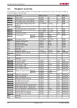
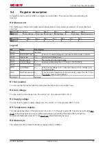
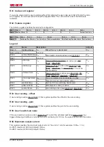
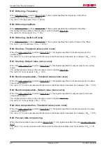
Access from the user program
5.1
Process image
The KL2535 and KL2545 appear in the complex process image with at least 6 bytes of input and 6 bytes of
output data. These are organized as follows:
Byte offset (without word
alignment)
Byte offset (with word align-
ment*)
Format
Input data
Output data
0
0
Byte
1
2
Word
DataIN1
DataOUT1
3
4
Byte
4
6
Word
DataIN2
DataOUT2
The KL2535 and KL2545 appear in the complex process image with at least 6 bytes of output data. These
are organized as follows:
Byte offset (without word
alignment)
Byte offset (with word align-
ment*)
Format
Input data
Output data
0
0
Byte
-
1
2
Word
-
DataOUT1
3
4
Byte
-
4
6
Word
-
DataOUT2
*) Word alignment: The Bus Coupler places values on even byte addresses
Legend
SB n: status byte channel n
CB n: Control byte of channel n
DataIN n: Input word of channel n
DataOUT n: Output word of channel n
Note
Process image
It is not possible for the KL2535 or KL2545 to operate without control bytes, since the con-
trol bytes are required to enable the channels. Even if you adjust your bus coupler to the
compact process image, the KL2535 and KL2545 will still be represented with their control
bytes!
Process data
Output value
Output current
-32767
dec
-100% of the maximum output current (see Register
)
0
dec
0
+32767
dec
+100% of the maximum output current (see Register
)
KL2535, KL2545
37
Version: 2.0.0
Содержание KL2535
Страница 1: ...Documentation KL2535 KL2545 Pulse width current terminals 2 0 0 2016 02 29 Version Date...
Страница 2: ......


