background image

Parameterization and commissioning

EL6751

94

Version: 3.5

Network Status

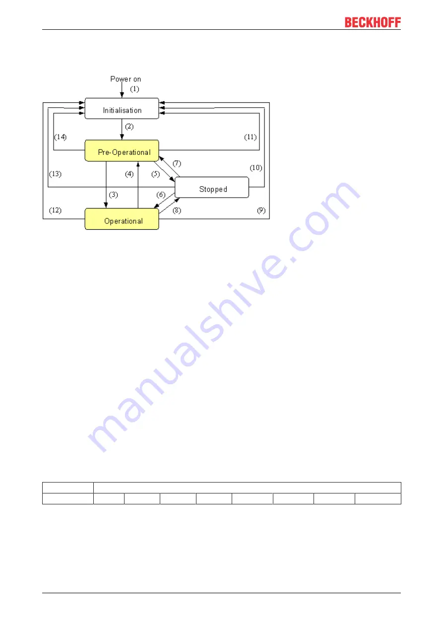
The states and the state transitions involved as CANopen boots up can be seen from the state diagram:

Fig. 111: CANopen bootup state diagram

Pre-Operational

After initialization the Bus Coupler goes automatically (i.e. without the need for any external command) into
the 

Pre-Operational

 state. In this state it can be configured, since the service data objects (SDOs) are

already active. The process data objects, on the other hand, are still locked.

Operational

In the 

Operational

 state the process data objects are also active.

If external influences (such as a CAN error, or absence of output voltage) or internal influences (such as a K-
Bus error) mean that it is no longer possible for the Bus Coupler to set outputs, to read inputs or to
communicate, it attempts to send an appropriate emergency message, goes into the error state, and thus
returns to the 

Pre-Operational

 state. In this way the NMT status machine in the network master can also

immediately detect fatal errors.

Stopped

In the 

Stopped

 state (formerly: 

Prepared

) data communication with the Coupler is no longer possible - only

NMT messages are received. The outputs go into the fault state.

State Transitions

The network management messages have a very simple structure: CAN identifier 

0

, with two bytes of data

content. The first data byte contains what is known as the command specifier (cs), and the second data byte
contains the node address, the node address 

0

 applying to all nodes (broadcast).

11 bit identifier 2 byte user data

0x00

cs

Node ID

The following table gives an overview of all the CANopen state transitions and the associated commands
(command specifier in the NMT master telegram):

Содержание EL6751

Страница 1: ...Documentation EL6751 Master Slave Terminal for CANopen 3 5 2019 07 12 Version Date...

Страница 2: ......

Страница 3: ...cumentation 26 3 8 UL notice 26 3 9 CANopen cabling 27 3 9 1 CAN topology 27 3 9 2 Bus length 27 3 9 3 Drop lines 28 3 9 4 Star Hub Multiport Tap 28 3 9 5 CAN cable 28 3 9 6 Shielding 30 3 9 7 Cable c...

Страница 4: ...and receiving of CAN Messages STD Frame Format via ADS 121 5 5 EtherCAT communication EL6751 122 5 5 1 CANopen master 122 5 5 2 CAN interface 154 6 Error handling and diagnostics 163 6 1 EL6751 LED de...

Страница 5: ...ion of products that have already been supplied may be made on the basis of the data diagrams and descriptions in this documentation Trademarks Beckhoff TwinCAT EtherCAT EtherCAT G EtherCAT G10 EtherC...

Страница 6: ...ined specialists in control automation and drive engineering who are familiar with the applicable national standards Description of instructions In this documentation the following instructions are us...

Страница 7: ...n Structural update 2 0 Technical data chapter updated Structural update 1 9 Addenda chapter Mounting and wiring 1 8 Addenda chapter Mounting and wiring 1 7 Addenda firmware compatibility 1 6 Addition...

Страница 8: ...rmation in the form of an XML file which is available for download from the Beckhoff web site From 2014 01 the revision is shown on the outside of the IP20 terminals see Fig EL5021 EL terminal standar...

Страница 9: ...hardware version of I O PCB 1 Unique serial number ID ID number In addition in some series each individual module has its own unique serial number See also the further documentation in the area IP67...

Страница 10: ...0020 with serial batch number 26131006 and unique ID number 204418 Fig 5 EP1258 00001 IP67 EtherCAT Box with batch number date code 22090101 and unique serial number 158102 Fig 6 EP1908 0002 IP67 Eth...

Страница 11: ...Version 3 5 Fig 7 EL2904 IP20 safety terminal with batch number date code 50110302 and unique serial number 00331701 Fig 8 ELM3604 0002 terminal with unique ID number QR code 100001051 and serial bat...

Страница 12: ...roduct it can be found in the following places on the packaging unit directly on the product if space suffices on the packaging unit and the product The BIC is machine readable and contains informatio...

Страница 13: ...y Beckhoff and serve internal processes Structure of the BIC Example of composite information from items 1 4 and 6 The data identifiers are marked in red for better display Fig 10 Structure of the BIC...

Страница 14: ...AN frames in the applications program The EL6751 is alternatively available in a master or slave version and has a powerful protocol implementation with many features All CANopen PDO communication typ...

Страница 15: ...rrent consumption via E bus typ 230 mA Electrical isolation 500 V E bus CANopen Configuration with TwinCAT System Manager Weight approx 70 g Permissible ambient temperature range during operation 25 C...

Страница 16: ...in this object directory is accessed via service data objects SDO There are additionally a few special objects such as telegram types for network management NMT synchronization error messages and so...

Страница 17: ...peaters which also allow the construction of tree structures Bus access procedures CAN utilizes the Carrier Sense Multiple Access CSMA procedure i e all participating devices have the same right of ac...

Страница 18: ...to EN 60715 3 2 Mounting and demounting terminals with traction lever unlocking The terminal modules are fastened to the assembly surface with the aid of a 35 mm mounting rail e g mounting rail TH 35...

Страница 19: ...it is not necessary to remove all the cables separately for this but for each KM EM connector simply undo 2 screws so that you can pull them off fixed wiring Lever the unlatching hook on the left han...

Страница 20: ...il TH 35 15 Fixing of mounting rails The locking mechanism of the terminals and couplers extends to the profile of the mounting rail At the installation the locking mechanism of the components must no...

Страница 21: ...he cables Demounting Remove all the cables Lever the unlatching hook back with thumb and forefinger 3 An internal mechanism pulls the two latching lugs 3a from the top hat rail back into the terminal...

Страница 22: ...tion requires the mounting rail to be installed horizontally and the connection surfaces of the EL KL terminals to face forward see Fig Recommended distances for standard installation position The ter...

Страница 23: ...minals in the bus terminal block EtherCAT Terminals ELxxxx ESxxxx which do not take an active part in data transfer within the bus terminal block are so called passive terminals The passive terminals...

Страница 24: ...Mounting and wiring EL6751 24 Version 3 5 Examples for positioning of passive terminals highlighted Fig 16 Correct positioning Fig 17 Incorrect positioning...

Страница 25: ...ect against the rated operating voltage being exceeded by more than 40 due to short term interference voltages The individual terminals may only be unplugged or removed from the Bus Terminal system if...

Страница 26: ...of the Beckhoff homepage http www beckhoff com 3 8 UL notice Application Beckhoff EtherCAT modules are intended for use with Beckhoff s UL Listed EtherCAT Sys tem only Examination For cULus examinatio...

Страница 27: ...two levels the CAN leads are not very sensitive to incoming interference EMI Both leads are affected so the interference has very little effect on the difference Fig 19 Insensitivity to incoming inter...

Страница 28: ...l drop lines 1 Mbit s 1 m 5 m 500 kbit s 5 m 25 m 250 kbit s 10 m 50 m 125 kbit s 20 m 100 m 50 kbit s 50 m 250 m Drop lines must not have terminating resistors Fig 20 Sample topology of drop lines 3...

Страница 29: ...marking length data every 20cm Fig 21 Structure of CAN cable ZB5100 ZB5200 CAN DeviceNet Cable The ZB5200 cable material corresponds to the DeviceNet specification and is also suitable for CANopen sy...

Страница 30: ...e will be transmitted from the mounting rail to the screen of the bus cable In that case the screen should not be attached to the couplers it should nevertheless still be fully connected through Notes...

Страница 31: ...s with the following pin assignment Pin Assignment 2 CAN low CAN 3 CAN ground internally connected to pin 6 6 CAN ground internally connected to pin 3 7 CAN high CAN The unlisted pins are not connecte...

Страница 32: ...lose to the supply potential Since the CANopen BK51X0 BX5100 Bus Couplers provide full electrical isolation of the bus connection it may in appropriate cases be possible to omit wiring up the CAN grou...

Страница 33: ...ply and then the CAN Check the cabling and only then switch on the voltage 3 9 11 Fieldbus Box M12 CAN socket The IPxxxx B510 IL230x B510 and IL230x C510 Fieldbus Boxes are connected to the bus using...

Страница 34: ...he device in each state particularly during the bootup of the slave A distinction is made between the following states Init Pre Operational Safe Operational and Operational Boot The regular state of e...

Страница 35: ...efore the EtherCAT master switches the EtherCAT slave from Safe Op to Op it must transfer valid output data In the Op state the slave copies the output data of the masters to its outputs Process data...

Страница 36: ...tion with the ESC from the application side The settings of the SM and PDI watchdog must be done for each slave separately in the TwinCAT System Manager Fig 29 EtherCAT tab Advanced Settings Behavior...

Страница 37: ...switches off completely This is the deactivation of the watchdog Set outputs are NOT set in a safe state if the communication is inter rupted 4 4 CoE Interface General description The CoE interface C...

Страница 38: ...E list it is shown in the TwinCAT System Manager as a separate tab with a listing of the elements Fig 30 CoE Online tab The figure above shows the CoE objects available in device EL2502 ranging from 0...

Страница 39: ...rted continuous changing of CoE values is not permissible in view of the lifetime limit Startup list Changes in the local CoE list of the terminal are lost if the terminal is replaced If a terminal is...

Страница 40: ...ssible The configured status is shown under Identity No firmware or hardware version is displayed since these are features of the physical device Offline is shown in red Fig 32 Offline list If the sla...

Страница 41: ...ation the placeholder n tends to be used for the individual channel numbers In the CoE system 16 indices each with 255 subindices are generally sufficient for representing all channel parameters The c...

Страница 42: ...eatures TwinCAT 3 eXtended Automation Visual Studio Integration Choice of the programming language Supports object orientated extension of IEC 61131 3 Usage of C C as programming language for real tim...

Страница 43: ...Interfaces listed under Compatible devices can be assigned a driver via the Install button A driver should only be installed on compatible devices A Windows warning regarding the unsigned driver can...

Страница 44: ...properties of the EtherCAT device can be opened by double click on Device EtherCAT within the Solution Explorer under I O After the installation the driver appears activated in the Windows overview f...

Страница 45: ...Parameterization and commissioning EL6751 45 Version 3 5 Fig 39 Exemplary correct driver setting for the Ethernet port Other possible settings have to be avoided...

Страница 46: ...Parameterization and commissioning EL6751 46 Version 3 5 Fig 40 Incorrect driver settings for the Ethernet port...

Страница 47: ...in cases where an EL6601 or similar devices are used it is useful to specify a fixed IP address for this port via the Internet Protocol TCP IP driver setting and to disable DHCP In this way the delay...

Страница 48: ...files that was current at the time when the TwinCAT build was created For TwinCAT 2 11 TwinCAT 3 and higher the ESI directory can be updated from the System Manager if the programming PC is connected...

Страница 49: ...the revision 1019 or for an older revision The ESI must then be requested from the manufacturer in this case Beckhoff b an ESI is present for the EL2521 0000 device but only in an older revision e g 1...

Страница 50: ...ould be deleted as follows close all System Manager windows restart TwinCAT in Config mode delete OnlineDescription0000 xml restart TwinCAT System Manager This file should not be visible after this pr...

Страница 51: ...ssioning EL6751 51 Version 3 5 Reasons may include Structure of the xml does not correspond to the associated xsd file check your schematics Contents cannot be translated into a device description con...

Страница 52: ...T slaves For the present publisher subscriber service in combination with an EL6601 EL6614 terminal select EtherCAT Automation Protocol via EL6601 Fig 49 Selecting the EtherCAT connection TwinCAT 2 11...

Страница 53: ...2 right TwinCAT 3 The dialog for selecting a new device opens Only devices for which ESI files are available are displayed Only devices are offered for selection that can be appended to the previously...

Страница 54: ...tended Information Fig 54 Display of device revision In many cases several device revisions were created for historic or functional reasons e g through technological advancement For simplification pur...

Страница 55: ...iguration This also enables subsequent replacement of devices without changing the configuration different specifications are possible for drives Example If an EL2521 0025 1018 is specified in the con...

Страница 56: ...Parameterization and commissioning EL6751 56 Version 3 5 Fig 57 EtherCAT terminal in the TwinCAT tree left TwinCAT 2 right TwinCAT 3...

Страница 57: ...g mode The online search is not available in RUN mode production operation Note the differentiation be tween TwinCAT programming system and TwinCAT target system The TwinCAT 2 icon or TwinCAT 3 icon w...

Страница 58: ...the type The respective devices are lo cated in the stored ESI data and integrated in the configuration tree in the default state defined there Fig 62 Example default state NOTE Slave scanning in prac...

Страница 59: ...nitial configuration B tsm in order to check the built machine However if the series machine production department now doesn t use B tsm but instead carries out a scan to create the productive configu...

Страница 60: ...en be switched to online state OPERATIONAL Fig 68 Config FreeRun query left TwinCAT 2 right TwinCAT 3 In Config FreeRun mode the System Manager display alternates between blue and red and the EtherCAT...

Страница 61: ...known device is detected i e an EtherCAT slave for which no ESI XML description is available In this case the System Manager offers to read any ESI that may be stored in the device This case is descri...

Страница 62: ...vice configuration is then replaced by the revision found this can affect the supported process data and functions If a scan is initiated for an existing configuration the actual I O environment may m...

Страница 63: ...expects based on the higher revision number Device selection based on revision compatibility The ESI description also defines the process image the communication type between master and slave device a...

Страница 64: ...ype TwinCAT offers a function Change to Compatible Type for the exchange of a device whilst retaining the links in the task Fig 77 Dialog Change to Compatible Type left TwinCAT 2 right TwinCAT 3 This...

Страница 65: ...therCAT Master uses the ESI description to configure the slave correctly The process data can be modified in the system manager See the device documentation Examples of modifications include mask out...

Страница 66: ...Notes EtherCAT Slave Application This summary briefly deals with a number of aspects of EtherCAT Slave operation under TwinCAT More detailed information on this may be found in the corresponding sect...

Страница 67: ...the PLC Colour Meaning yellow Input variables from the Slave to the EtherCAT Master updated in every cycle red Output variables from the Slave to the EtherCAT Master updated in every cycle green Info...

Страница 68: ...Parameterization and commissioning EL6751 68 Version 3 5 Fig 81 Basic EtherCAT Slave Diagnosis in the PLC The following aspects are covered here...

Страница 69: ...ay possibly have effects on the process data of other Slaves that are located in the same Syn cUnit In order for the higher level PLC task or cor responding control applications to be able to rely on...

Страница 70: ...re saved locally in the slave depends on the device EL terminals except the EL66xx are able to save in this way The user must manage the changes to the StartUp list Commissioning aid in the TwinCAT Sy...

Страница 71: ...nd manual operation After the operating power is switched on an EtherCAT Slave must go through the following statuses INIT PREOP SAFEOP OP to ensure sound operation The EtherCAT Master directs these s...

Страница 72: ...ter are set as standard EtherCAT Master OP Slaves OP This setting applies equally to all Slaves Fig 84 Default behaviour of the System Manager In addition the target state of any particular Slave can...

Страница 73: ...er and slave Fig 86 PLC function blocks Note regarding E Bus current EL ES terminals are placed on the DIN rail at a coupler on the terminal strand A Bus Coupler can supply the EL terminals added to i...

Страница 74: ...11 and above a warning message E Bus Power of Terminal is output in the logger window when such a configuration is activated Fig 88 Warning message for exceeding E Bus current NOTE Caution Malfunctio...

Страница 75: ...ions without TwinCAT PLC or NC the TwinCAT System Manager Tool configures the programming interfaces for a wide range of application programs ActiveX control ADS OCX for e g Visual Basic Visual C Delp...

Страница 76: ...ow Cost Bus Coupler BK5150 Compact Bus Coupler BK5151 Compact Bus Coupler with D Sub connection BC5150 Compact Bus Terminal Controller with 48 kbyte program memory BX5100 BX Bus Terminal Controller wi...

Страница 77: ...hen the mapping is generated Sync Cycle Multiplier CANopen SYNC Cycle Time Task Cycle Time x Sync Cycle Multiplier Event driven PDO communications and cyclical synchronized PDO communication are frequ...

Страница 78: ...in the EtherCAT slave controller are updated The later this is the case the shorter the dead time from receipt of a TxPDO until the time when the associated input data of the task are available The m...

Страница 79: ...ws the current firmware version of the EL6751 Firmware Update FC510x only The firmware update is carried out via the associated hardware ADS tab The EL6751 is an ADS device with its own net ID which c...

Страница 80: ...figuration of the CAN interface Fig 95 Can Queue Sizes setting Tx queue and Rx queue define the number of messages that are exchanged between the task and the CANopen master in a task cycle If the mes...

Страница 81: ...Message 11 Bit Identifier 1 extended Message 29 Bit Identifier Data 8 Message structure without 29 bit support CobId o Bit 0 3 Length 0 8 o Bit 4 RTR o Bit 5 15 11 Bit Identifier Data 8 The CAN Rx Fil...

Страница 82: ...esToSend do Outputs TxMessage i MessageToSend i End_for Outputs NoOfTxMessages NumberOfMessagesToSend Outputs TxCounter Outputs TxCounter 1 end_if Sample code Receiving messages from the PLC if Output...

Страница 83: ...CANopenSlave TwinCAT searches for the terminal and displays the memory addresses and slots it finds Select the required address and confirm I O Device EL6751 0010 CANopen Slave Selecting the inserted...

Страница 84: ...current EL6751 0010 firmware version Firmware Update FC510x only The firmware update for the EL6751 0010 is carried out via the associated EL6751 0010 terminal ADS tab The EL6751 0010 is an ADS devic...

Страница 85: ...DeviceType that can be read via object 0x1000 Configuring network variables PLC variables communicated by the EL6751 0010 device are referred to as network variables These variables must be created a...

Страница 86: ...the variables for the different tasks 5 3 2 BECKHOFF CANopen Bus Coupler The BK51xx Bus Coupler and the IPxxx B510 Fieldbus Box are installed in the CANopen bus The specific properties which distingui...

Страница 87: ...ed with this Inhibit Time 101 Event Time Event timer for transmit PDOs Expiry of this timer is treated as an additional event for the corresponding PDO so that the PDO will then be transmitted If the...

Страница 88: ...set contains the CANopen Sub Index See chapter SDO communication 114 for details of SDO communication via ADS Diag tab Diagnostic information is displayed here The window contents are not cyclically r...

Страница 89: ...stem start do not comply with the values present the StartUp of this node will be interrupted and a corresponding error message will appear in the Diag Tab Guard time The guard time determines the int...

Страница 90: ...O addressing is not possible in this mode no response No NMT stop remote node command after node error Node Restart Automatic Restart After a recognized node error the card automatically attempts to r...

Страница 91: ...ical PDOs Is entered in multiples of 0 1 ms Length The length of the PDO is based on the mapped variables and cannot therefore be edit here Event time FC510x and EL6751 only Enter the value for the Ev...

Страница 92: ...riables are inserted one after another you need to set the corresponding offset start address within the CAN telegram for each variable Object dictionary entries in TwinCAT TwinCAT places the PDOs in...

Страница 93: ...ad and write SDO objects using ADS read requests and or write requests The ADS IndexGroup contains the CANopen object index and the ADS IndexOffset contains the CANopen Sub Index 5 4 CANopen Communica...

Страница 94: ...Coupler to set outputs to read inputs or to communicate it attempts to send an appropriate emergency message goes into the error state and thus returns to the Pre Operational state In this way the NM...

Страница 95: ...following telegram resets node 17 11 bit identifier 2 byte of user data 0x00 0x81 0x11 Boot up message After the initialization phase and the self test the Bus Coupler sends the boot up message which...

Страница 96: ...be monitored These reply with the guarding message This contains the slave s status code and a toggle bit that has to change after every message If either the status or the toggle bit do not agree wi...

Страница 97: ...calculated from the guard time object 0x100C and life time factor object 0x100D parameters Life time guard time x life time factor If either of these two parameters is 0 the default setting the maste...

Страница 98: ...value other than the configured value is read Upload Revision Number 0x1018 03 The entry 0x1018 03 of the CANopen slave is read and compared with the configured value if this not equal 0 This SDO is...

Страница 99: ...ed on the PDO 88 tab of the respective PDO For Bus Couplers there is only one inhibit time for all PDOs if the PDOs are configured via the object 0x5500 The SDOs are active if this inhibit time on tab...

Страница 100: ...urred during the download of the producer heartbeat If the SDO is active the startup is aborted if an SDO abort has occurred Download further startup SDOs Further startup SDOs are written All further...

Страница 101: ...wice the event time the node state is set to 22 and the CANopen slave is treated according to the configured error response Error response If a fault is detected in a CANopen slave during TxPDO monito...

Страница 102: ...al dynamically organizes the process image i e the process data are written in succession enabling a higher data transmission rate Up to 32 TxPDOs and 32 RxPDOs can be handled in slave mode For each e...

Страница 103: ...allocation must be appropriately adapted so that the TxPDO identifier of the producer agrees with the RxPDO identifier of the consumer This procedure is known as PDO linking It permits for sample eas...

Страница 104: ...stance through a monitoring or diagnostic device brought into the network while it is running The time behavior of remote frame and response telegrams depends on what CAN controller is in use Componen...

Страница 105: ...ansmission type 0 function synchronously but not cyclically An RxPDO is only evaluated after the next SYNC telegram has been received In this way for instance axis groups can be given new target posit...

Страница 106: ...re the CAN controllers sometimes answer remote frames automatically without first requesting up to date input data there are circumstances in which it is questionable whether the polled data is up to...

Страница 107: ...tion 109 PDO Mapping PDO mapping refers to mapping of the application objects real time data from the object directory to the process data objects The CANopen device profile provide a default mapping...

Страница 108: ...data can be freely allocated to the PDOs The mapping tables must be configured for this as from Version 4 of CANopen only the following procedure is permitted and must be followed precisely 1 First d...

Страница 109: ...ntages and disadvantages Cyclic synchronous communication provides an accurately predictable bus loading and therefore a defined time behavior you could say that the standard case is the worst case It...

Страница 110: ...ch other closely on the bus at 1 Mbit s this can generate an interrupt every 40 s for example an NMT master might transmit all its guarding requests in an unbroken sequence This can be avoided through...

Страница 111: ...icient one telegram pair For a download the client sends the data together with its index and sub index and the server confirms reception For an upload the client requests the data by transmitting the...

Страница 112: ...dex1 SubIdx Data0 Data1 Data2 Data3 Parameter Explanation Index0 Index low byte Unsigned16 LSB Index1 Index high byte Unsigned16 MSB SubIdx Sub index Unsigned8 Data0 Data low low byte LLSB Data3 Data...

Страница 113: ...4 00 43 General parameter incompatibility 0x06 04 00 47 General internal error in device 0x06 06 00 00 Access interrupted due to hardware error 0x06 07 00 10 Data type or parameter length do not agree...

Страница 114: ...d the SDO the terminal then attempts to read the corresponding value back and to compare it with the value that was to be written This is because it could for instance be a read only value and therefo...

Страница 115: ...triggered by a rising edge at this input TIMEOUT States the time before the function is cancelled BUSY This output remains TRUE until the function block has executed a command but at the longest for...

Страница 116: ...ses the CANopen Node see System Manager CO_Index DWORD This is the Index of the CANopen Object Dictionary Entry CO_SubIndex DWORD This is the Sub Index of the CANopen Object Dictionary Entry DataLengt...

Страница 117: ...WRITE WriteDataFinished THEN WriteStart FALSE WriteError SDO_WRITE Error END_IF The SDO_WRITE function block that has been called in turn calls the ADSWRITE function a number of times It looks like th...

Страница 118: ...OUT T 1s IF ADSWrite err THEN state 2 WriteDataFinished TRUE Error ADSWrite ErrId ELSE state 1 END_IF ELSE ADSWrite NETID PORT PortNr IDXGRP CO_Index IDXOFFS CO_SubIndex LEN DataLength SRCADDR ADR Wri...

Страница 119: ...JA1000 Intel 80C527 Siemens 80C167 and other CAN controllers They are optimized for the maximum bus length 5 4 8 Identifier Allocation Default identifier CANopen provides default identifiers for the m...

Страница 120: ...at boot up message 1110 0x701 0x77F 1793 1919 0x100C 0x100D 0x100E 0x1016 0x1017 For historical reasons the Beckhoff default mapping applies to PDOs 3 and 4 in Beckhoff I O devices In most configurati...

Страница 121: ...s The option of sending any CAN messages via the IndexGroup 0xF923 has been extended by a function of receiving CAN messages 5 4 10 Sending and receiving of CAN Messages STD Frame Format via ADS Sendi...

Страница 122: ...ing the received CAN messages AdsRead NETID AoeNetId der EL6751 PORT 200 IDXGRP 16 F921 IDXOFFS 0 LEN 640 maximum buffer size The DATA has the same structure when sending the CAN messages The buffer i...

Страница 123: ...e flash memory of the EL6751 and need only be transmitted once Configuration of the EL6751 with StartUp SDOs The following flow chart shows the sequence of the configuration of the EL6751 with StartUp...

Страница 124: ...t the EL6751 has calculated itself The writing of the PDO mapping thus serves only to check the PDO mapping calculated by the EtherCAT configurator and can therefore be omitted PDO Assign In addition...

Страница 125: ...N bus The scanning of the CAN bus can be started in the PREOP state provided that no CANopen configuration has been loaded yet To this end the desired baud rate must be written to entry 0xF002 01 SDO...

Страница 126: ...objects 0x8yyz from them and proceed according to the Configuration of the EL6751 with StartUp SDOs 123 Creating the Backup Parameter Storage As an alternative to reading the InfoData the Backup Para...

Страница 127: ...eceived are stored as Backup Parameter Storage in the flash memory 2 Scan the CAN bus and then write the value 0x65766173 to entry 0x1010 01 here the EL6751 automatically generates the Backup Paramete...

Страница 128: ...PDOs a delay can be set for the TxPDOs in 0xF800 0E After sending the SYNC message the EL6751 waits until this delay has expired before sending any further CAN messages After that the synchronous RxPD...

Страница 129: ...ure that the EtherCAT input data can be copied completely before the next EtherCAT cycle begins otherwise the working the counter would not be okay Synchronization with SYNC0 SYNC1 event The Distribut...

Страница 130: ...1 After the TxPDO delay has expired on the flow chart it is assumed that the TxPDO delay is smaller than the input shift time transmission of the synchronous RxPDOs begins If the input shift time expi...

Страница 131: ...Process Data tab allocation of PDOs Please note the following general CoE notes 37 when using manipulating the CoE parameters Keep a startup list if components have to be replaced Differentiation bet...

Страница 132: ...ation for identifying the slave UINT8 RO 0x04 4dec 1018 01 Vendor ID Vendor ID of the EtherCAT slave UINT32 RO 0x00000002 2dec 1018 02 Product code Product code of the EtherCAT slave UINT32 RO 0x1A5F3...

Страница 133: ...n1 2 m Index of the object of the 3rd StartUp SDO m 1 len3 Length of the object of the 3rd StartUp SDO as CompleteAccess from SubIndex 0 in bytes m 2 n3 Data of the object of the 3rd StartUp SDO as Co...

Страница 134: ...06 Exclude TxPDOs Specifies the TxPDOs index of TxPDO mapping objects that must not be transferred together with TxPDO 131 OCTET STRING 14 RO 80 1A 00 00 00 00 00 00 00 00 00 00 00 00 Index 1883 TxPD...

Страница 135: ...andatory and must always be contained in the PDO As sign object 0x1C13 139 depending on the configured CANopen slaves SubIndex 0 contains the number of CAN RxPDOs of the n 1 th configured CANopen slav...

Страница 136: ...2 RO 0xF103 01 1 1A82 m Diag Flag of the last mth configured CANopen slave configured via the objects 0x800z m 1 16 1 m 127 UINT32 RO 0xF103 m 1 Index 1A83 TxPDO Map Node State Index hex Name Meaning...

Страница 137: ...bIndex 009 9 PDO Mapping entry 8 bits align UINT32 RO 0x0000 00 8 1A84 0A SubIndex 010 10 PDO Mapping entry object 0xF101 Extended Diag entry 0x14 Cycle Time UINT32 RO 0xF101 14 16 1A84 0B SubIndex 01...

Страница 138: ...Index 011 11 PDO Mapping entry object 0xF108 CAN Status entry 0x22 TX error counter UINT32 RO 0xF108 22 8 Index 1A88 TxPDO Map CAN TxPDO Toggle 1 Index hex Name Meaning Data type Flags Default 1A88 0...

Страница 139: ...TxPDO assign Index hex Name Meaning Data type Flags Default 1C13 0 TxPDO assign PDO Assign Inputs the TxPDOs must be assigned in the order of their indexes The TxPDOs of the configured CANopen slaves...

Страница 140: ...vent in ns DC mode only UINT32 RO 0x00000000 0dec 1C32 08 Command 0 Measurement of the local cycle time is stopped 1 Measurement of the local cycle time is started The entries 0x1C32 03 140 0x1C32 05...

Страница 141: ...me Time between reading of the inputs and availability of the inputs for the master in ns only DC mode UINT32 RO 0x00000000 0dec 1C33 08 Command as 0x1C32 08 140 UINT16 RW 0x0000 0dec 1C33 09 Delay ti...

Страница 142: ...a type Flags Default 7000 n 16 0 CAN RxPDOs Node yyy This object contains the CAN RxPDOs 1 255 of the n 1 th configured CANopen slave The corresponding SubIndex is only present if the corresponding CA...

Страница 143: ...gs reserved for AMS via CANopen UINT16 RW 0x0000 0dec 8000 n 16 1E Network port reserved for AMS via CANopen UINT16 RW 0x0000 0dec 8000 n 16 1F Network segment ad dress reserved for AMS via CANopen OC...

Страница 144: ...he CANopen slave must be restarted via AoE 8000 n 16 28 Master reaction after CANopen fault If an error is determined during communication with the CANopen slave the CANopen communication with the oth...

Страница 145: ...ning Data type Flags Default 8006 n 16 0 CAN TxPDO Configuration Node yyy This object contains the CAN TxPDO configuration of the n 1 th configured CANopen slave 0 n 127 TxPDOs 1 255 of a CANopen slav...

Страница 146: ...e OCTET STRING 12 RW Index 9000 97D0 Detected CANopen Identification Node yyy Index hex Name Meaning Data type Flags Default 9000 n 16 0 Detected CANopen Identification Node yyy This object contains t...

Страница 147: ...08 n 16 0 Detected RxPDO Configuration Node yyy This object contains the InfoData on the CAN RxPDOs of the n 1 th found CANopen slave if the Scan Boxes com mand has been executed following switching t...

Страница 148: ...sending of Start Node Bit 6 CAN TxPDO 7 was not received at least once after the sending of Start Node Bit 7 CAN TxPDO 8 was not received at least once after the sending of Start Node Bit 8 CAN TxPDO...

Страница 149: ...mergencies Node yyy Index hex Name Meaning Data type Flags Default A002 n 16 0 CANopen Emergen cies Node yyy for each CANopen slave configured in 0x8000 n 16 there is an object that contains the recei...

Страница 150: ...found slaves Byte 4 Node address of the first CANopen slave found Bytes 5 8 Vendor ID of the first CANopen slave found Bytes 9 12 Product code of the first CANopen slave found Byte 13 Node address of...

Страница 151: ...e Index hex Name Meaning Data type Flags Default F102 0 Node State There is a node state for each CANopen slave config ured in 0x8000 n 16 The node states are mapped in Tx PDO 132 Index 0x1A83 136 UIN...

Страница 152: ...7F Diag Flag of the last configured CANopen slave BOOLEAN RW Index F108 CAN Status Index hex Name Meaning Data type Flags Default F108 0 CAN status This object contains the CAN status that is mapped i...

Страница 153: ...hich the SYNC message can be sent UINT32 RO F120 11 Ouput Calc and Copy Maximum Time max T1 maximum time after the start of the CAN cycle at which the SYNC message can be sent UINT32 RO F120 12 Input...

Страница 154: ...AN controller byte 2 must be 0 byte 3 must be 0 F800 06 Slave Mode must be 0 CANopen master BOOLEAN RW 0x00 0dec F800 07 PDO Align 8 Bytes 0 CAN PDOs are appended to the EtherCAT process data in succe...

Страница 155: ...tion and commissioning EL6751 155 Version 3 5 Fig 131 Flow chart for CAN interface startup After a power on the EL6751 is in the INIT state and has no CAN configuration The CAN controller is in the OF...

Страница 156: ...d that the EtherCAT PDOs of the CAN interface must appear in the PDO Assign With regard to the order of the PDOs in the PDO Assign it is important to ensure that the index of the assigned EtherCAT PDO...

Страница 157: ...x700z 01 Subsequently the CAN Rx messages received since the last increment of the RxCounter in the EtherCAT input data are entered in the EtherCAT input data provided that the RxCounter in the EtherC...

Страница 158: ...delayed until the SYNC1 event occurs so that the sending of the first CAN Tx message takes place with a jitter of maximum 500 ns The output delay time is the time between the SYNC1 event and the start...

Страница 159: ...up parameter handling 10F2 133 Backup parameter storage 1600 160 RxPDO Map CAN Interface 1685 134 RxPDO Map CAN Control 1A00 160 TxPDO Map CAN Interface 1A85 138 TxPDO Map CAN Status 1C00 138 Sync man...

Страница 160: ...Index 1A00 TxPDO Map CAN Interface Index hex Name Meaning Data type Flags Default 1A00 0 TxPDO Map CAN In terface The CAN interface is mapped into the EtherCAT input data with this PDO The number of b...

Страница 161: ...ansaction Num ber see CAN interface description UNT16 RO 6001 05 RX Message 1 see CAN interface description OCTET STRING 14 RO 6001 m RX Message m 4 see CAN interface description OCTET STRING 14 RO In...

Страница 162: ...e 150 UINT16 RW 0x0096 150dec Index 8001 CAN Rx filter table From firmware 17 of the EL6751 parameter 0x8001 must be written with valid values If all data are to be written into the CAN interface the...

Страница 163: ...State Machine SAFEOP verification of the sync manager channels and the distributed clocks Outputs remain in safe state on State of the EtherCAT State Machine OP normal operating state mailbox and proc...

Страница 164: ...ehensive range of diagnostic options for connected network nodes Fig 135 Diagnosis of inputs in the TwinCAT tree For each CANopen fieldbus node there is a node state input variable which signals the s...

Страница 165: ...rtUp in progress Node was found and has been started 11 0x0B EL6751Bus OFF CAN chip has entered the Bus OFF state transmit error counter is running 12 0x0C Pre Operational Node has gone pre operationa...

Страница 166: ...guarding is activated 6 Toggling missed several times and guarding activated Bit 5 15 Associated COB ID Offset 6 Bit 0 7 1 Incorrect value during SDO upload 2 Incorrect length during SDO upload 3 Abor...

Страница 167: ...overflow for SDOs guarding heartbeat etc Bit 5 CAN transmission error this bit is set when no data can be transmitted e g if the EL6751 connector is unplugged Bit 7 internal Rx queue full the data are...

Страница 168: ...Hi Word Node Number IndexOffset See below Length See below If more than 26 bytes of diagnostic data have been read out the emergency memory is reset The DiagFlag is reset as soon as at least 108 bytes...

Страница 169: ...allowed in INIT state 0x1116 Incorrect IndexOffset at DeleteBox 0x1117 Incorrect data length at DeleteBox 0x1118 ReadBox only with AdsRead 0x1119 AddCdl not allowed in INIT state 0x111A Incorrect dat...

Страница 170: ...02 AddBox Insufficient memory for ADS StartUp telegram 0x1604 DeleteBox Box is not stopped 0x1605 AddBox Insufficient memory for CDL telegram 0x1606 AddBox Number of CDL telegrams is too large 0x1607...

Страница 171: ...ime must be greater than the cycle time 0x1802 StartFieldbus Cycle time is too large 0x1803 StartFieldbus Cycle time is too large 0x1804 StartFieldbus Shift time is too large 0x1805 StartFieldbus PLL...

Страница 172: ...AddCdl Incorrect telegram index 0x2011 AddBox Too many Rx or Tx PDOs 0x2012 AdsRead Incorrect IndexGroup 0x2013 AdsRead Incorrect IndexOffset 0x2014 AdsRead Incorrect length 0x2015 AdsWrite Incorrect...

Страница 173: ...for instance one node contributes unusually heavily to the bus traffic e g because it is the only one with analog inputs the data for which triggers event driven PDOs at a high rate then the prob abi...

Страница 174: ...ors or faulty transceivers Test 4 Check for a short circuit between the CAN ground and the signal leads or between the screen and signal leads Test 5 Remove the earth connection from the CAN ground an...

Страница 175: ...m potential difference between any two devices should be less than 5 volts Detect and localize faults The low tech approach usually works best disconnect parts of the network and observe when the faul...

Страница 176: ...mers with free firmware updates for delivered products NOTE Risk of damage to the device Pay attention to the instructions for firmware updates on the separate page 177 If a device is placed in BOOTST...

Страница 177: ...unication is set up accordingly The device description is available from the download area of the Beckhoff website at https www beckhoff de All ESI files are accessible there as zip files Customers ca...

Страница 178: ...evice description has a unique identifier consisting of slave name 9 characters digits and a revision number 4 digits Each slave configured in the System Manager shows its identifier in the EtherCAT t...

Страница 179: ...uration is identical otherwise a change dialog appears for entering the actual data in the configuration Fig 143 Change dialog In this example in Fig Change dialog an EL3201 0000 0017 was found while...

Страница 180: ...d in the following dialog see Fig Selecting the new ESI The checkbox Show Hidden Devices also displays older normally hidden versions of a slave Fig 145 Selecting the new ESI A progress bar in the Sys...

Страница 181: ...terminal 2 EL3204 and select the tab CoE Online CAN over EtherCAT CoE Online and Offline CoE Two CoE directories are available online This is offered in the EtherCAT slave by the controller if the Eth...

Страница 182: ...ring a firmware update Switch to the Online tab to update the controller firmware of a slave see Fig Firmware Update Fig 147 Firmware Update Proceed as follows unless instructed otherwise by Beckhoff...

Страница 183: ...date may be accomplished via an rbf file Controller firmware for processing I O signals FPGA firmware for EtherCAT communication only for terminals with FPGA The firmware version number included in th...

Страница 184: ...right click the table header and select Properties in the context menu Fig 149 Context menu Properties The Advanced Settings dialog appears where the columns to be displayed can be selected Under Dia...

Страница 185: ...terminal must have FPGA firmware version 10 or higher Older firmware versions can only be updated by the manufacturer Updating an EtherCAT device The following sequence order have to be met if no othe...

Страница 186: ...nager select the terminal for which the FPGA firmware is to be updated in the example Terminal 5 EL5001 and click the Advanced Settings button in the EtherCAT tab The Advanced Settings dialog appears...

Страница 187: ...the device A download of firmware to an EtherCAT device must not be interrupted in any case If you interrupt this process by switching off power supply or disconnecting the Ethernet link the EtherCAT...

Страница 188: ...o 0xBF 0xFF TxPDO1 189 385 to 447 511 0x181 to 0x1BF 0x1FF RxPDO1 190 513 to 575 639 0x201 to 0x23F 0x27F TxPDO2 191 641 to 676 767 0x281 to 0x2BF 0x2FF RxPDO2 192 769 to 831 895 0x301 to 0x33F 0x37F...

Страница 189: ...d 42 dec hex Telegram type dec hex Telegram type dec hex Telegram type 385 0x181 TxPDO1 DI Nd 1 406 0x196 TxPDO1 DI Nd 22 427 0x1AB TxPDO1 DI Nd 43 386 0x182 TxPDO1 DI Nd 2 407 0x197 TxPDO1 DI Nd 23 4...

Страница 190: ...0 563 0x233 RxPDO1 DO Nd 51 522 0x20A RxPDO1 DO Nd 10 543 0x21F RxPDO1 DO Nd 31 564 0x234 RxPDO1 DO Nd 52 523 0x20B RxPDO1 DO Nd 11 544 0x220 RxPDO1 DO Nd 32 565 0x235 RxPDO1 DO Nd 53 524 0x20C RxPDO1...

Страница 191: ...0 691 0x2B3 TxPDO2 AI Nd 51 650 0x28A TxPDO2 AI Nd 10 671 0x29F TxPDO2 AI Nd 31 692 0x2B4 TxPDO2 AI Nd 52 651 0x28B TxPDO2 AI Nd 11 672 0x2A0 TxPDO2 AI Nd 32 693 0x2B5 TxPDO2 AI Nd 53 652 0x28C TxPDO2...

Страница 192: ...0 819 0x333 RxPDO2 AO Nd 51 778 0x30A RxPDO2 AO Nd 10 799 0x31F RxPDO2 AO Nd 31 820 0x334 RxPDO2 AO Nd 52 779 0x30B RxPDO2 AO Nd 11 800 0x320 RxPDO2 AO Nd 32 821 0x335 RxPDO2 AO Nd 53 780 0x30C RxPDO2...

Страница 193: ...BE TxPDO3 Nd 62 917 0x395 TxPDO3 Nd 21 938 0x3AA TxPDO3 Nd 42 959 0x3BF TxPDO3 Nd 63 dec hex Telegram type dec hex Telegram type dec hex Telegram type 1025 0x401 RxPDO3 Nd 1 1046 0x416 RxPDO3 Nd 22 10...

Страница 194: ...0x4A9 TxPDO4 Nd 41 1214 0x4BE TxPDO4 Nd 62 1173 0x495 TxPDO4 Nd 21 1194 0x4AA TxPDO4 Nd 42 1215 0x4BF TxPDO4 Nd 63 dec hex Telegram type dec hex Telegram type dec hex Telegram type 1281 0x501 RxPDO4...

Страница 195: ...0x6A9 TxPDO5 Nd 41 1726 0x6BE TxPDO5 Nd 62 1685 0x695 TxPDO5 Nd 21 1706 0x6AA TxPDO5 Nd 42 1727 0x6BF TxPDO5 Nd 63 dec hex Telegram type dec hex Telegram type dec hex Telegram type 1921 0x781 RxPDO5...

Страница 196: ...20 489 0x1E9 TxPDO6 Nd 41 510 0x1FE TxPDO6 Nd 62 469 0x1D5 TxPDO6 Nd 21 490 0x1EA TxPDO6 Nd 42 511 0x1FF TxPDO6 Nd 63 dec hex Telegram type dec hex Telegram type dec hex Telegram type 577 0x241 RxPDO...

Страница 197: ...745 0x2E9 TxPDO7 Nd 41 766 0x2FE TxPDO7 Nd 62 725 0x2D5 TxPDO7 Nd 21 746 0x2EA TxPDO7 Nd 42 767 0x2FF TxPDO7 Nd 63 dec hex Telegram type dec hex Telegram type dec hex Telegram type 833 0x341 RxPDO7 N...

Страница 198: ...1 1022 0x3FE TxPDO8 Nd 62 981 0x3D5 TxPDO8 Nd 21 1002 0x3EA TxPDO8 Nd 42 1023 0x3FF TxPDO8 Nd 63 dec hex Telegram type dec hex Telegram type dec hex Telegram type 1089 0x441 RxPDO8 Nd 1 1110 0x456 RxP...

Страница 199: ...0x4E9 TxPDO9 Nd 41 1278 0x4FE TxPDO9 Nd 62 1237 0x4D5 TxPDO9 Nd 21 1258 0x4EA TxPDO9 Nd 42 1279 0x4FF TxPDO9 Nd 63 dec hex Telegram type dec hex Telegram type dec hex Telegram type 1345 0x541 RxPDO9...

Страница 200: ...9 TxPDO10 Nd 41 1534 0x5FE TxPDO10 Nd 62 1493 0x5D5 TxPDO10 Nd 21 1514 0x5EA TxPDO10 Nd 42 1535 0x5FF TxPDO10 Nd 63 dec hex Telegram type dec hex Telegram type dec hex Telegram type 1601 0x641 RxPDO10...

Страница 201: ...9 TxPDO11 Nd 41 1790 0x6FE TxPDO11 Nd 62 1749 0x6D5 TxPDO11 Nd 21 1770 0x6EA TxPDO11 Nd 42 1791 0x6FF TxPDO11 Nd 63 dec hex Telegram type dec hex Telegram type dec hex Telegram type 1857 0x741 RxPDO11...

Страница 202: ...0x5A9 SDO Tx Nd 41 1470 0x5BE SDO Tx Nd 62 1429 0x595 SDO Tx Nd 21 1450 0x5AA SDO Tx Nd 42 1471 0x5BF SDO Tx Nd 63 dec hex Telegram type dec hex Telegram type dec hex Telegram type 1537 0x601 SDO Rx...

Страница 203: ...0 1843 0x733 Guarding Nd 51 1802 0x70A Guarding Nd 10 1823 0x71F Guarding Nd 31 1844 0x734 Guarding Nd 52 1803 0x70B Guarding Nd 11 1824 0x720 Guarding Nd 32 1845 0x735 Guarding Nd 53 1804 0x70C Guard...

Страница 204: ...ne of the service primitives of the CANopen specification Network management is used to initialize the network and to monitor nodes OP OPERATIONAL PDO Process Data Object A CAN telegram for the transf...

Страница 205: ...how with Comparative Resources Franzis Verlag 2001 244 pages ISBN 3 7723 5745 8 English books Konrad Etschberger Controller Area Network Ixxat Press 2001 440 pages ISBN 3 00 007376 0 M Farsi M Barbos...

Страница 206: ...components there Beckhoff Headquarters Beckhoff Automation GmbH Co KG Huelshorstweg 20 33415 Verl Germany Phone 49 5246 963 0 Fax 49 5246 963 198 e mail info beckhoff com Beckhoff Support Support off...

Страница 207: ...dard installation position 22 Fig 15 Other installation positions 23 Fig 16 Correct positioning 24 Fig 17 Incorrect positioning 24 Fig 18 Termination of the bus with a 120 Ohm termination resistor 27...

Страница 208: ...58 Fig 62 Example default state 58 Fig 63 Installing EthetCAT terminal with revision 1018 59 Fig 64 Detection of EtherCAT terminal with revision 1019 59 Fig 65 Scan query after automatic creation of a...

Страница 209: ...inserting further Tx or Rx PDOs 92 Fig 110 SDOs tab 93 Fig 111 CANopen bootup state diagram 94 Fig 112 Schematic diagram Guarding procedure 96 Fig 113 Schematic diagram Heartbeat procedure 97 Fig 114...

Страница 210: ...139 Wiring diagram for test setup 174 Fig 140 Device identifier consisting of name EL3204 0000 and revision 0016 178 Fig 141 Scan the subordinate field by right clicking on the EtherCAT device 179 Fig...

Отзывы: