6 / 32
REV. 01
CHAPTER 2
– GENERAL INFORMATION
2.1
INTENDED USE
•
This Semi-
automatic tire changer has been designed and manufactured exclusively for
removing and mounting tires from/onto rims from 12" to 26" and a maximum diameter of
1200 mm.
•
In
particular
THE MANUFACTURER
cannot be held responsible for any damage caused
through the use of this tire changer for purposes other than those specified in this manual, and
therefore inappropriate, incorrect and unreasonable.
2.2
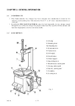
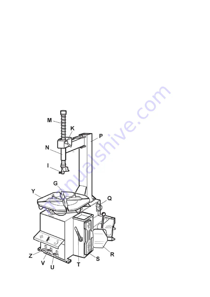
DESCRIPTION
G) Clamps
I) Mounting head
M) Mounting bar
N) Horizontal arm
P) Vertical arm
Q) Air supply
R) Bead breaker
S) Wheel support
T) Bead lifting lever
U) Bead breaker control pedal
V) Clamp control pedal
Z) Reverse control pedal
Y) Turntable
K) Locking lever
Fig . 1
Содержание 70-030
Страница 7: ...7 32 REV 01 2 3 DANGER WARNING SIGNS...
Страница 30: ...CHAPTER 9 ELECTRIC AND PNEUMATIC DIAGRAM STANDARD ELECTRIC DIAGRAM...
Страница 31: ...STANDARD PNEUMATIC SYSTEM DIAGRAM...


