CHAPTER 7
– MAINTENANCE
7.1 GENERAL WARNINGS
Unauthorized personnel may not carry out maintenance work.
•
Regular maintenance as described in the manual is essential for correct operation and long
lifetime of the tire changer.
•
If maintenance is not carried out regularly, the operation and reliability of the machine may be
compromised, thus placing the operator and anyone else in the vicinity at risk.
Disconnect the electric and pneumatic supplies before carrying out
any maintenance work. It is necessary to operate the bead breaker without load
3-4
times in order to release the air pressure from the circuit.
•
Defective parts must be replaced exclusively by authorized personnel using the
manufacturer’s original parts.
•
Removing or tampering with safety devices (pressure limiting and regulating valves) is
forbidden.
In particular the Manufacturer shall not be held responsible for
complaints deriving from the use of spare parts made by other manufacturers or
for damage caused by tampering or removal of safety systems.
7.2 MAINTENANCE OPERATIONS
•
Clean the turntable once a week with diesel fuel so as to prevent the formation of dirt, and
lubricate the clamp sliding guides.
•
Carry out the following operations at least every 30 days:
•
Check the oil level in the lubricator tank. If necessary, fill up by unscrewing the reservoir
F. Only use ISO VG viscosity ISOHG class oil for compressed air circuit. (Fig. 14)
•
Check that a drop of oil is injected into the reservoir F very 3-4 times the pedal U is
pressed down. If not, regulate using the screw D (fig. 14)
•
After the first 20 days of work, retighten the clamp tightening screws on the turntable slides
•
(Fig. 15).
•
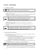
In the event of a loss of power, check that the drive belt is tight as follows.
Before any operation disconnect the electric power supply.
•
Remove the left side body panel of the tire changer by unscrewing the four fixing screws.
•
Remove the drive belt by means of the special adjusting screw X on the motor support (Fig.
16).
Содержание 70-030
Страница 7: ...7 32 REV 01 2 3 DANGER WARNING SIGNS...
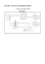
Страница 30: ...CHAPTER 9 ELECTRIC AND PNEUMATIC DIAGRAM STANDARD ELECTRIC DIAGRAM...
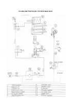
Страница 31: ...STANDARD PNEUMATIC SYSTEM DIAGRAM...

