15
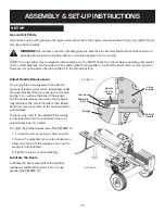
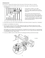
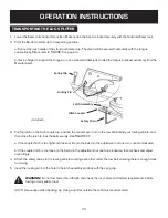
3. Adjust the engine side of coupler shaft to make sure the engine key fits into the slot of the coupler
shaft, and tighten the set screw just loosened.
4. If needed, slowly ull on the engine starter cord to rotate the engine shaft to align the fixing holes on the
pump mount with the holes on the engine. Also make sure the open side of the pump mount facing down.
5. Secure the pump assembly onto the engine using the bolts 5/16-24 and M8 washers. Tighten the
hardware using a 1/2 ” wrench.
Page 12
3. Adjust the engine side of coupler shaft to make sure the engine key fits into the slot of the coupler shaft, a
nd tighten
the set screw just loosened.
4. If needed, slowly ull on the engine starter cord to rotate the engine shaft to align the fixing holes on the pump mount
with the holes on the engine. Also make sure the open side of the pump mount facing down.
5. Secure the pump assembly onto the engine using the bolts
5/16-24 and M8 washers.
Tighten the hardware using
a 1/2 ” wrench.
REF. NO.
DECSRIPTION
QTY.
6
Engine assembly (in engine box), including:
1
6-1
Engine
1
6-2
Engine shaft key
1
7
Hardware Kit # 8-1 (22 /
25 / 28T
) or # 8-2 (30 / 35T),
1
7-1
Pump mount assembly / 11GPM or Pump mount assembly / 16GPM
1
7-2
Hex head bolt / 5/16-24 Same
4
7-3
Spring washer / 5/16 Same
4
7-4
Flat washer / M8 Same
4
STEP 4:
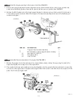
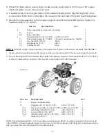
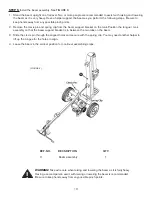
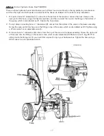
Install the engine / pump assembly to the engine mount plate on the reservoir assembly. See FIGURE 7.
1. Insert a vibration isolator between the engine and the mount plate at each of the four mounting hole positions.
2. Secure the engine with the hardware, then tighten the harware using two 13mm wrenches for 22 / 25 / 28 ton model;
or 16mm wrench on bolts, 17mm wrench on lock nuts for 30 / 35 ton model.
REF. NO. DECSRIPTION
QTY.
9
Engine / Pump assembly
1
10
Hardware kit # 5-1 (22 /
25 / 28T
)
or # 5-2 (30 / 35T),
i l di
1
10-1
Hex head bolt / M8 x 40 (22 /
25 / 28T
) or M10 x 40 (30 / 35T)
4
10-2
Flat washer / M8 (22 /
25 / 28T
)
or M10 (30 / 35T)
8
10-3
Lock nut / M8 (22 /
25 / 28T
) or M10 (30 / 35T)
4
10-4
Vibration isolator /
Ø9 (22 / 25 / 28T) or Ø11 (30 / 35T)
4
//
O Seal ring /
Ø15*1.9
1
NOTE:
In the Hardware Kit # 5-1 or 5-2,
you have one O seal ring /
Ø15*1.9, which is
a spare O ring to be used
in the “
STEP 6:
Connect hydraulic hoses” section if you can’t find one sitting in the fitting slot on the
reservoir tank, when you attach the oil return hose
③
to the reservoir tank.
(FIGURE 7)
Page 15
STEP 4:
Install the engine / pump assembly to the engine mount plate on the reservoir assembly. See FIGURE 7.
1. Insert a vibration isolator between the engine and the mount plate at each of the four mounting hole positions.
2. Secure the engine with the hardware, then tighten the harware using two 13mm wrenches for 22 / 25 / 28 ton
model; or 16mm wrench on bolts, 17mm wrench on lock nuts for 30 / 35 ton model.
NOTE:
In the Hardware Kit # 5-1 or 5-2, you have one O seal ring / Ø15*1.9, which is a spare O ring to be used
in the “STEP 6: Connect hydraulic hoses” section if you can’t find one sitting in the fitting slot on the reservoir tank,
when you attach the oil return hose (3) to the reservoir tank.
Содержание Agri Ease BE-25TLE65GX
Страница 34: ...31 EXPLODED DIAGRAM PARTS LIST Page 28 EXPLODED DIAGRAM PARTS LIST Page 31...
Страница 39: ......

