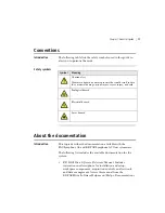
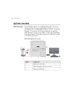
BD FACSymphony A3 Скачать руководство пользователя страница 18

User’s Guide

18

Components

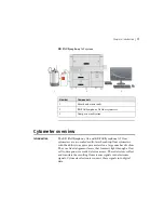
The following figures show the main components of each 
instrument. Each component is described in detail in the following 
sections.

BD FACSymphony A3

8

2

3

6

4

5

9

7

1

Number

Component

Number

Component

1

Heat ventilation slots (top)

6

Sample injection port (SIP)

2

Control panel

7

Heat ventilation slots (side)

3

Power button

8

Air and fluidic ports

4

Electrical plug

9

Optics access door (decagon 

or 

cascade 

detector arrays) left side

5

Fluidic sensors

Содержание FACSymphony A3

Страница 1: ...iosciences 2350 Qume Drive San Jose CA 95131 USA bdbiosciences com ResearchApplications bd com BD Biosciences European Customer Support Tel 32 2 400 98 95 Fax 32 2 401 70 94 help biosciences europe bd...

Страница 2: ...you require a commercial license to use this product and do not have one return this material unopened to BD Biosciences 2350 Qume Dr San Jose CA 95131 and any money paid for the material will be ref...

Страница 3: ...the EMC and the Low Voltage Directives This includes FCC Part 15 compliance for a Class A Digital Device CAUTION Any unauthorized modifications to this laboratory equipment may affect the Regulatory C...

Страница 4: ......

Страница 5: ...16 Cytometer overview 17 Control panel 20 Fluidics system 21 Sheath and waste containers 28 Optics 29 Workstation 31 Chapter 3 Cytometer setup 33 Starting the cytometer and computer 34 Preparing the s...

Страница 6: ...mizing cytometer settings 63 Cytometer settings workflow 64 Verifying the configuration and user preferences 66 Running a performance check 68 Setting up an experiment 72 Creating application settings...

Страница 7: ...pter 8 Manual settings 111 About laser delay 112 Optimizing laser delay 113 Adjusting area scaling 115 Chapter 9 Supplies and consumables 121 Ordering information 122 Beads 122 Reagents 123 Equipment...

Страница 8: ...User s Guide 8...

Страница 9: ...1 About this guide This chapter covers the following topics What this guide covers page 10 Conventions page 11 About the documentation page 11 Instrument technical support page 13...

Страница 10: ...essa X 50 flow cytometers respectively Because many cytometer functions are controlled by BD FACSDiva software this guide also contains information about software features required for basic cytometer...

Страница 11: ...llowing list includes the available documentation for the system BD FACSDiva Software Reference Manual Includes instructions or descriptions for installation and setup workspace components acquisition...

Страница 12: ...uirements The FACSymphony A3 and BD FACSymphony A5 Flow Cytometers Safety and Limitations Provides descriptions of safety and warning labels general system hazards specific risks and laser electrical...

Страница 13: ...local BD Biosciences customer support representative or supplier Visit our website bdbiosciences com for up to date contact information When contacting BD Biosciences have the following information a...

Страница 14: ...This page intentionally left blank...

Страница 15: ...2 Introduction This chapter covers the following topics System overview page 16 Cytometer overview page 17 Control panel page 20 Fluidics system page 21 Sheath and waste containers page 28 Optics pag...

Страница 16: ...or BD FACSDiva software v8 0 1 1 or later for Windows 7 running on the system workstation the optional BD FACSFlow supply system FFSS and the optional BD High Throughput Sampler HTS Each component is...

Страница 17: ...o acquire parameters for a large number of colors They use fixed alignment lasers that transmit light through a flow cell to decagon or cascade detector arrays These detectors collect and translate th...

Страница 18: ...he following sections BD FACSymphony A3 8 2 3 6 4 5 9 7 1 Number Component Number Component 1 Heat ventilation slots top 6 Sample injection port SIP 2 Control panel 7 Heat ventilation slots side 3 Pow...

Страница 19: ...ber Component Number Component 1 Heat ventilation slots top 6 Sample injection port SIP 2 Control panel 7 Heat ventilation slots side 3 Power button 8 Air and fluidic ports 4 Electrical plug 9 Optics...

Страница 20: ...any objects on top of the instrument Blocking the ventilation may cause the instrument to overheat Caution Electrical Hazard Do not place liquids on top of the instrument Any spill of liquid into the...

Страница 21: ...ors There are two system indicators System status and Activity on the control panel System status Shows the status of the sheath and waste tank levels The following table describes the LED indicators...

Страница 22: ...sample tube the cytometer switches to an automatic standby status to conserve sheath fluid and the Run button changes to orange Standby Stops fluid flow to conserve sheath fluid When you leave the cy...

Страница 23: ...ple fine adjust buttons When sample adj is set to 250 as shown on the status screen on the control panel the sample flow rates at the low med and high settings are approximately 12 35 and 60 L min of...

Страница 24: ...Status screen The first two lines of the status screen show the level of the waste and sheath tanks The third line toggles between three different displays and is described in detail in the following...

Страница 25: ...turns yellow at 80 and red at 100 full 2 Sheath level Shows range from E to F The display line decreases from right to left in sequences of 20 from full level System status turns yellow at 20 and red...

Страница 26: ...injection tube Outer sleeve Sample injection tube Tube support arm Sample injection tube Stainless steel tube that carries sample from the sample tube to the flow cell This tube is covered with an out...

Страница 27: ...ction tube Caution Biohazard When using the flow cytometers with the HTS ensure that the HTS is completely pushed into the operating position before removing the droplet containment module DCM sleeve...

Страница 28: ...h container The sheath container has a capacity of 10 L Sheath fluid is filtered through an in line interchangeable filter that prevents small particles from entering the sheath fluid lines An alarm s...

Страница 29: ...t the corresponding number of signals Laser options The flow cytometers can be configured with up to five lasers on the BD FACSymphony A3 or 10 lasers on the BD FACSymphony A5 The laser wavelengths an...

Страница 30: ...ic filters LPs Transmit wavelengths that are longer than the specified value and reflect all light below the specified wavelength Bandpass filters BPs Pass a narrow spectral band of light When dichroi...

Страница 31: ...re are two types of signal detectors in the BD FACSymphony A3 and BD FACSymphony A5 flow cytometers PMTs Used to detect the weaker signals generated by side scatter SSC and all fluorescence channels T...

Страница 32: ...nclude a PC one or two monitors and a printer Your workstation is equipped with the following Microsoft Windows operating system BD FACSDiva software version 9 1 or later for Windows 10 or BD FACSDiva...

Страница 33: ...ing the cytometer and computer page 34 Preparing the sheath container page 35 Removing air bubbles page 37 Preparing the waste container page 40 Priming the fluidics page 42 About the optical filters...

Страница 34: ...ure to stabilize 3 Turn on the computer and log in to Windows Note You can turn on the power to the flow cytometer and the workstation in any order 4 Start BD FACSDiva software by double clicking the...

Страница 35: ...eshooting page 110 Preparing the sheath container Introduction This topic describes how to prepare the sheath container Note If your system is using the FFSS see the documentation provided with your s...

Страница 36: ...e the sheath container 1 Verify that the flow cytometer is in standby mode Press the STANDBY button on the control panel if necessary 2 Disconnect the green air line sheath fluid line and alarm sensor...

Страница 37: ...e gasket is not seated correctly the tank will not pressurize properly 9 Close the sheath lid and tighten the clamp knob to finger tight Ensure that the blue sheath fluid line is not kinked More infor...

Страница 38: ...nt line Vent fitting Cytometer fluid line roller clamp not visible 2 If bubbles are visible gently tap the filter body with your fingers to dislodge the bubbles and force them to the top Caution When...

Страница 39: ...empties from the filter Button Vent fitting 4 Tilt the filter and verify that no trapped air remains in the filter 5 Repeat steps 3 and 4 until no air is observed in the filter 6 Check the sheath line...

Страница 40: ...provided with your FFSS Waste container components The following figure shows the main components of the waste container Alarm sensor Waste fluid line with metal clip Air line Caution Biohazard All b...

Страница 41: ...it on the bench label side up when it is not on the tank Procedure To prepare the waste container 1 Verify that the flow cytometer is in standby mode Press the STANDBY button on the control panel if n...

Страница 42: ...ics 1 Move the tube support arm to the side 2 Remove the tube from the SIP 3 Press the PRIME fluid control button to force the fluid out of the flow cell and into the waste container Once drained the...

Страница 43: ...ly The optic holder in front of the last PMT in the detector array contains only a bandpass filter and is marked accordingly PMT Optic holder handle Optic holders The filters steer progressively short...

Страница 44: ...on Before you acquire data using BD FACSDiva software you must specify a cytometer configuration The cytometer configuration defines which filters and mirrors are installed at each detector BD FACSDiv...

Страница 45: ...of your cytometer A baseline provides a starting point for the tracking of cytometer performance When running a performance check you compare the results to the baseline See Optimizing cytometer sett...

Страница 46: ...This page intentionally left blank...

Страница 47: ...eaning the fluidics page 49 Shutting down the cytometer page 51 Flushing the system page 52 Replacing the waste container cap page 54 Changing the sheath filter page 56 Changing the Bal seal page 58 C...

Страница 48: ...ble regulations and manufacturer specifications Dispose of waste using proper precautions and in accordance with local regulations Never pipette by mouth For fluidics maintenance we recommend the foll...

Страница 49: ...ch as Hoechst DAPI propidium iodide PI acridine orange AO or thiazole orange TO Procedure To clean the fluidics 1 Press RUN and HIGH on the cytometer fluid control panel 2 Install a tube containing 3...

Страница 50: ...I water 6 Press the STANDBY button on the fluidics control panel 7 Place a tube containing no more than 1 mL of DI water on the SIP A tube with 1 mL of DI water should remain on the SIP to prevent sal...

Страница 51: ...down the cytometer 1 Place a tube of DI water on the SIP 2 Turn off the flow cytometer 3 Select Start Shutdown to turn off the computer if needed 4 If your system is connected to the FFSS shut off the...

Страница 52: ...e filter assembly c Connect the two fluid lines 2 Empty the sheath container and rinse it with DI water 3 Fill the sheath container with at least 1 L of undiluted BD FACSClean solution 4 Empty the was...

Страница 53: ...support arm underneath the tube See Maintenance overview page 48 for other recommended cleaning solutions 9 Press RUN and HIGH on the cytometer fluid control panel Run for 30 minutes 10 Press the STAN...

Страница 54: ...y it Wait at least 30 seconds for pressure to dissipate before you remove the waste cap or sensor Expose waste container contents to bleach 10 of total volume for 30 minutes before disposal Procedure...

Страница 55: ...r and hand tighten until it is fully closed Re attach the alarm sensor line and waste line to the waste container tank Caution Biohazard To prevent waste container overpressurization do not overtighte...

Страница 56: ...ntainer When to change the sheath filter We recommend changing the sheath filter assembly every six months Increased debris appearing in an FSC vs SSC plot can indicate that the sheath filter needs to...

Страница 57: ...filter 1 Connect the vent line to the new filter assembly Twist to attach 2 Wrap Teflon tape around the filter threads then connect the filter to the filter base 3 Connect the sheath line to the filt...

Страница 58: ...when a sample tube is installed on the SIP Indications that a proper seal has not formed include The tube will not stay on the SIP without the tube support arm When the tube is installed and RUN is pr...

Страница 59: ...tainer and outer sleeve over the sample injection tube Push the outer sleeve all the way up into the sample injection port and then screw the retainer into place and tighten to finger tight This will...

Страница 60: ...he O ring when droplets form at the end of the sample injection tube while the vacuum is operating Caution Procedure To change the O ring 1 Remove the outer sleeve from the sample injection tube by tu...

Страница 61: ...4 Place the new O ring into the retainer Make sure the O ring is seated properly in the bottom of the retainer 5 Replace the outer sleeve in the retainer 6 Re install the retainer and the outer sleeve...

Страница 62: ...the sheath gasket when needed Procedure To clean or replace the gasket 1 Put the cytometer in standby mode 2 Depressurize the sheath container by pulling up on the vent valve 3 Remove the lid from the...

Страница 63: ...Cytometer settings workflow page 64 Verifying the configuration and user preferences page 66 Running a performance check page 68 Setting up an experiment page 72 Creating application settings page 78...

Страница 64: ...ion setup automatically calculates compensation settings If you choose to perform compensation manually not all of the following instructions apply For detailed instructions see the BD FACSDiva Softwa...

Страница 65: ...ou follow this workflow with a different bead sample or another sample type your software views data plots and statistics might differ from the example Additionally you might need to modify some of th...

Страница 66: ...e an experiment 1 Select Cytometer View Configurations and verify the current configuration Your cytometer might include only the base configuration when your cytometer is installed You can create add...

Страница 67: ...set matches your flow cytometer optics 3 Click OK to close the Cytometer Configuration window 4 Select File Exit to close CS T 5 Select Edit User Preferences 6 Click the General tab and select the Lo...

Страница 68: ...ics performance We strongly recommend following the fluidics maintenance procedures as described in Cleaning the fluidics page 49 Considerations Some BP filters might not be normalized to CS T setting...

Страница 69: ...configuration a Click Select Configuration in the Setup Control window b Select the correct configuration from the list c Click Set Configuration and then click OK 4 Verify that the current configurat...

Страница 70: ...Low Plots appear under the Setup tab and the performance check is run The performance check takes approximately 5 minutes to complete 10 Once the performance check is complete click View Report 11 Ve...

Страница 71: ...iva interface The CST Mismatch dialog opens Click the Details button to verify which cytometer settings will be updated 13 Click Use CST Settings By selecting Use CST Settings the laser delay area sca...

Страница 72: ...following windows as needed Browser Cytometer Inspector Worksheet Acquisition Dashboard When you add elements or make selections in the Browser the Inspector displays details properties and options t...

Страница 73: ...settings 73 5 Select MyExperiment in the Browser The Inspector displays details for the experiment Specifying parameters To specify the parameters for the new experiment 1 Select Cytometer Settings fo...

Страница 74: ...ings appear in the Inspector 2 Make sure the parameters you need appear on the Parameters tab in the Inspector If more than one parameter is available for a particular PMT you might have to select the...

Страница 75: ...Chapter 5 Optimizing cytometer settings 75 example you can set Detector F for the blue laser as FITC or BB515 a Click the Parameter name to display the available fluorochromes in the Parameters list...

Страница 76: ...User s Guide 76 b Select the specific parameter from the menu Your selection appears as the selected parameter c For this example select FITC from the menu 3 Delete any unnecessary parameters...

Страница 77: ...Chapter 5 Optimizing cytometer settings 77 a Click the selection button to the left of the parameter name to select the parameter b Click Delete The parameter is deleted...

Страница 78: ...run Using application settings provides a consistent and reproducible way to reuse cytometer settings for commonly used applications You can include area scaling adjustment in your application settin...

Страница 79: ...thout interfering with the population of interest If needed increase the fluorescence PMT voltages to place the negative population within the gray boxes Align the center of the negative population wi...

Страница 80: ...lticolor sample 8 Place a tube containing DI water on the SIP and put the cytometer on standby 9 Optional Save the application settings by right clicking Cytometer settings in the Browser then selecti...

Страница 81: ...the Compensation Setup feature of BD FACSDiva software and an experiment with optimized settings Creating compensation tubes To create compensation control tubes 1 Select Experiment Compensation Setu...

Страница 82: ...1 Press RUN and HIGH on the cytometer fluid control panel 2 Install the unstained control tube onto the SIP 3 Expand the Compensation Controls specimen in the Browser 4 Set the current tube pointer to...

Страница 83: ...cord Data 9 When recording is finished remove the unstained control tube from the cytometer 10 Click Next Tube 11 Install the next tube onto the cytometer and repeat steps 8 through 10 until data for...

Страница 84: ...lating compensation page 84 Calculating compensation Introduction This topic describes how to calculate compensation Before you begin Before you can calculate compensation you need to record the data...

Страница 85: ...he setup name The compensation setup is linked to the MyExperiment cytometer settings and subsequent acquisitions in MyExperiment are performed with the new compensation settings We recommend that you...

Страница 86: ...This page intentionally left blank...

Страница 87: ...and analyzing data This chapter covers the following topics Data recording and analysis workflow page 88 Preparing the workspace page 89 Recording data page 90 Analyzing data page 93 Reusing an analy...

Страница 88: ...are window content names of folders and experiments and your data plots and statistics might differ from those shown here You might also need to modify some of the instructions in the procedure For ad...

Страница 89: ...in MyExperiment to access the default global worksheet and rename the worksheet MyData 4 On the MyData worksheet create the following plots for previewing the data FSC vs SSC FITC vs PE FITC vs PerCP...

Страница 90: ...e renamed application settings and the cytometer settings icon in the Browser changes More information Creating application settings page 78 Recording data page 90 Recording data Introduction This top...

Страница 91: ...C vs SSC plot b Rename the P1 gate to Singlets c Use the Inspector to set the other plots to show only the singlet population by selecting the Singlets checkbox 6 Click Record Data 7 When event record...

Страница 92: ...similar to the previous sample 12 Click Record Data 13 When event recording has completed remove the second tube from the cytometer 14 If you are recording more than two tubes repeat steps 8 through 1...

Страница 93: ...it MyDataAnalysis 2 Create the following plots on the MyDataAnalysis worksheet FSC vs SSC FITC vs PE FITC vs PerCP Cy5 5 FITC vs APC 3 Create a population hierarchy and a statistics view and set them...

Страница 94: ...User s Guide 94 7 Select all plots except the FSC vs SSC plot and use the Plot tab in the Inspector to show only the singlet population 8 Select all plots and click the Title tab in the Inspector...

Страница 95: ...elect the Tube and Populations checkboxes to display their names in plot titles 10 On all fluorescence plots Make all plots biexponential Select all fluorescence plots and select the X Axis and Y Axis...

Страница 96: ...e population PerCP Cy5 5 positive in the population hierarchy In the FITC vs APC plot draw a gate around the APC positive population Name the population APC positive in the population hierarchy 11 For...

Страница 97: ...Chapter 6 Recording and analyzing data 97 e Click OK 12 Print the analysis...

Страница 98: ...User s Guide 98 Your global worksheet analysis objects should look like the following...

Страница 99: ...tube 2 View the Beads_002 data on your analysis worksheet Adjust the gates as needed Adjustments apply to subsequent tubes viewed on the worksheet To avoid altering a global worksheet save an analysi...

Страница 100: ...ysis objects from the MyDataAnalysis global worksheet are copied to the Beads_001_Analysis normal worksheet Double click the Beads_001 tube in the Browser to view the analysis Applying an analysis to...

Страница 101: ...7 Troubleshooting This chapter covers the following topics Cytometer troubleshooting page 102 Electronics troubleshooting page 110...

Страница 102: ...oosen the retainer 2 Push the outer sleeve up into the retainer until seated 3 Tighten the retainer Outer sleeve is not on the sample injection tube Replace the outer sleeve 1 Loosen the retainer 2 Sl...

Страница 103: ...t module is failing Try the solutions in Droplets are visible on the SIP page 102 If the issue is not resolved call your BD service representative Possible causes Recommended solutions Threshold is no...

Страница 104: ...e the sample tube to allow backflushing If the event rate is still erratic clean the sample injection tube See Cleaning the fluidics page 49 Bal seal is worn Replace the Bal seal See Changing the Bal...

Страница 105: ...ll connectors are securely seated Inspect the sheath container O ring inside the lid and replace it if necessary See Cleaning or replacing the sheath gasket page 62 Bal seal is worn Replace the Bal se...

Страница 106: ...Software Reference Manual for instructions PMT voltage for the threshold parameter is set too high Set the PMT voltage lower for the threshold parameter See the BD FACSDiva Software Reference Manual...

Страница 107: ...ge 49 Possible causes Recommended solutions Possible causes Recommended solutions Sample tube is cracked Replace the sample tube Air bubble or debris in the flow cell Prime the fluidics system See Pri...

Страница 108: ...t the sheath container lid is tight and all connectors are secure Hypertonic buffers or fixative Replace the buffers or fixative Possible causes Recommended solutions Threshold level is too low Increa...

Страница 109: ...ow cell is dirty Flush the system See Flushing the system page 52 Waste tank is pressurized Replace the waste container cap See Replacing the waste container cap page 54 Poor sample preparation Repeat...

Страница 110: ...w Possible causes Recommended solutions Cytometer power is off Turn on the cytometer main power Communication failure between workstation and cytometer 1 In BD FACSDiva software select Cytometer Conne...

Страница 111: ...8 Manual settings This chapter covers the following topics About laser delay page 112 Optimizing laser delay page 113 Adjusting area scaling page 115...

Страница 112: ...r intercepts the stream first followed by the violet UV and red lasers Because the laser signals are spatially separated there is a slight delay between the detection of each laser s signal Time Red E...

Страница 113: ...cedures in Recording and analyzing data page 87 for sample optimization and acquiring data Procedure To optimize laser delay 1 While acquiring data from your sample create a histogram to show the fluo...

Страница 114: ...he histogram adjust the laser delay in 1 s increments You might need to adjust the delay above or below the initial setting Choose the setting that moves the events farthest to the right highest fluor...

Страница 115: ...portant to verify that the area calculation and the height measurement are equivalent by adjusting the factor applied to the area The required area scaling factor changes based on sheath pressure and...

Страница 116: ...ect the height for each parameter 4 On the global worksheet create the following plots and histograms FSC vs SSC dot plot FSC H and FSC A histogram FITC H and FITC A histogram APC H and APC A histogra...

Страница 117: ...tic views showing the following FSC H and FSC A means for P1 FITC H and FITC A means for P1 APC H and APC A means for P1 Your worksheet should look similar to the following figure 7 Expand the new spe...

Страница 118: ...and SSC voltages to place the particles on scale 10 Adjust the P1 gate around the population of interest 11 Adjust the FSC area scaling a Click the Laser Tab in the Cytometer window b Adjust the FSC...

Страница 119: ...l is higher than FSC H c View the result of your change in the histograms and statistics views 12 Adjust the blue laser area scaling factor until the FITC A signal matches the FITC H signal if needed...

Страница 120: ...User s Guide 120 14 Adjust the red laser area scaling factor until the APC A signal matches the APC H signal if needed...

Страница 121: ...9 Supplies and consumables This chapter covers the following topics Ordering information page 122 Beads page 122 Reagents page 123 Equipment page 124...

Страница 122: ...sentative Worldwide contact information can be found at bdbiosciences com Beads Introduction This topic lists the QC and CS T beads available QC particles Particle Laser Supplier Catalog No SPHERO Rai...

Страница 123: ...tests 655051 150 tests Reagent Supplier Catalog No BD FACSFlow sheath fluid BD Biosciences 342003 BD FACS sheath solution with surfactant recommended for use with the HTS option BD Biosciences 336524...

Страница 124: ...5 sodium hypochlorite Clorox or other major supplier to ensure that the bleach is at the correct concentration and free of particulate matter Reagent Supplier Catalog No Equipment item Supplier Catal...

Страница 125: ...low sheath fluid 123 BD FACSFlow solution 37 BD FACSFlow supply system 34 51 BD FACSRinse solution 50 BD High Throughput Sampler HTS 27 blank optical holders 43 bleach 48 124 BP See bandpass filters b...

Страница 126: ...troubleshooting 110 event rate erratic 107 high 106 low 106 zero 103 105 excessive debris 108 experiments creating 72 immunophenotyping 89 sample optimization 72 specifying parameters 73 F FACSFlow s...

Страница 127: ...em flush 52 mirrors dichroic longpass LP filter 30 O optic holder 43 optics components 29 configuration 66 67 filters 30 optimization sample 64 ordering spare parts 122 O ring ordering 124 replacing 6...

Страница 128: ...th container components shown 36 defined 28 depressurize 36 preparing 36 sheath filter components shown 56 ordering 124 removing air bubbles 37 replacing 56 sheath fluid backflush 27 BD FACSFlow sheat...

Отзывы: