background image

38

BD CARV II Installation and User’s Guide

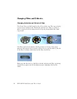
Confocal Disk (stopped)

–If the confocal disk is out of the light 

path, pressing this button both moves the confocal disk into the 
light path and starts it spinning. This is represented on the touch 
pad when the following graphic “moves over” the FRAP iris into 
the light path. If the disk is in the light path, pressing this button 
moves the disk out of the light path. Turning the disk motor on 
via software will change the graphic to the following icon (that 
is, the spinning confocal disk) but will not change the disk 
position.

Confocal Disk (spinning)

–This button is displayed when the 

confocal disk is spinning. This can be either in or out of the light 
path if controlled by the computer. Pressing this button with the 
disk in the light path stops it spinning and moves it out of the 
light path. The FRAP Iris button is restored. Turning the disk 
motor off via software will change the graphic to the previous 
icon but will not change the position.

NOTICE     

The confocal disk graphic only indicates 

if the disk is spinning or not. Its location indicates 
whether or not it is in or out of the light path. 
Button presses will move the disk in or out of the 
light path, stopping the disk if it's out, spinning the 
disk if it's in. Independent control of the disk is 
accomplished with computer commands.

Camera

–Press this button to direct the light path to the camera 

port. The prism graphic changes as described in the 

Prism 

(camera)

 section that follows.

Binoculars

–This button will direct the light path to the 

binoculars, or bincos. The prism graphic changes as described in 
the 

Prism (binocs)

 section that follows. Pressing and holding this 

button for about four seconds activates the prism slider 
calibration buttons. Refer to the calibration section (Calibrating 
the Prism on page 47) for more 
details.

Prism (camera)

–When the prism is out of the light path, the light 

path is directed to the camera. Pressing either the binoc button, 
this prism button, or commanding the prism using the software, 
will move the prism into the light path to direct it to the binocs. 
The prism graphic will change to the one below.

Содержание CARV II

Страница 1: ... Tel 55 11 5185 9995 Fax 55 11 5185 9895 Europe Tel 32 53 720211 Fax 32 53 720452 Mexico Tel 52 55 5999 8296 Fax 52 55 5999 8288 Japan Nippon Becton Dickinson Company Ltd Tel 0120 8555 90 Asia Pacific Fax 65 6 860 1590 Canada Tel 888 259 0187 Fax 905 542 9391 Tel 65 6 861 0633 905 542 8028 canada bd com BD CARV II Confocal Imager Installation and User s Guide ...

Страница 2: ...istered trademark of the Universal Imaging Corporation Microsoft and Windows are registered trademarks of Microsoft Corporation Texas Red is a registered trademark of Molecular Probes Invitrogen X Cite is a trademark of Electro Optical Engineering Inc EXFO All other company and product names might be trademarks of the respective companies with which they are associated Patents CARV II 6 147 798 an...

Страница 3: ...lation 13 BD CARV II Components 14 Filter Wheel Assembly 18 Filter Descriptions 19 Changing the Filter Wheels 21 Changing Filters and Dichroics 24 Binocular Assembly 27 Touch Pad Controller Assembly 27 Light Source EXFO X Cite 120 Assembly 28 CARV II Attachment to Microscope 29 Camera Attachment 29 Camera Focus Adjustment 30 Focusing the Pinholes 30 ...

Страница 4: ...CARV II Screens 39 Eight Position Filter Wheel Screens 39 Dichroic Wheel Screen 41 Intensity Iris Screen 42 FRAP Iris Screen 44 Presets Screen 46 Calibration 47 Calibrating the Prism 47 Calibrating the Confocal Disk 48 Calibrating the Filter Wheels 49 Chapter 4 BD CARV II Command Sets 51 Software Communications 52 Devices 52 Command Conventions 53 Command Formats 55 Index Index 1 ...

Страница 5: ...5 1 BD CARV II Hardware The following topics are covered in this chapter BD CARV II Description BD CARV II Specifications BD CARV II Light Path ...

Страница 6: ...ectrum 360nm 700nm confocal imaging Synchronous automation of an eight position excitation wheel a five position dichroic wheel and an eight position emission wheel allows for fast multi wavelength confocal imaging This eliminates the use of multi band pass filter sets and provides maximum light throughput and fast sequential imaging BD CARV II can be used with most high end interline or frame tra...

Страница 7: ...uses all of the optics and motors the CARV II also has a touch pad controller which controls virtually all the input output for the system The light source is an EXFO X Cite 120W Hg metal halide lamp which delivers light to the CARV II via a 1 5 M EXFO liquid light guide ...

Страница 8: ...osition wheel 25 7x36 mm Internal Emission Changer automated eight position wheel 25 mm Filter Sets Provided DAPI E GFP TEXAS RED Semrock Bright line series Operation Mode automated confocal wide field bright field Observation direct confocal binocular viewing or camera port Detector Compatibility CCD camera Sensicam EM QE Cooke Coolsnap HQ Cascade 512B Photometrics ORCA ER AG Hamamatsu and more M...

Страница 9: ...ardware 9 Figure 1 1 Complete System Mounted on an Olympus IX 71 Microscope with a Hamamatsu Ocra ER Camera Size 11 w x 15 5 L x 6 h inches 27 94 w x 39 37 L x 15 24 cm Weight 14 5 lbs 6 6Kg Power 100 240 VAC 1 2 A 50 60 Hz ...

Страница 10: ...Arc Lamp The light source is an EXFO X Cite 120W Hg metal halide lamp which delivers light to the CARV II via a 1 5 M EXFO liquid light guide The liquid light guide delivery system produces even illumination and eliminates the need for arc lamp alignment The lamp has typical Hg arc spectral characteristics and has a life of 1200 hours Shutter The illumination shutter can be controlled via the touc...

Страница 11: ... available 25 mm filters Filter positions can be controlled via the touch pad controller or via RS232 commands software control Spinning Disk The Nipkow spinning disk can be moved in and out of the light path allowing both confocal images and wide field images to be obtained The spinning disk can be controlled via the touch pad controller or via RS232 commands software control FRAP Slit The adjust...

Страница 12: ...12 BD CARV II Installation and User s Guide ...

Страница 13: ...this chapter BD CARV II Components Filter Wheel Assembly Filter Descriptions Changing Filters and Dichroics Binocular Assembly Touch Pad Controller Assembly Light Source EXFO X Cite 120 Assembly CARV II Attachment to Microscope Camera Attachment Camera Focus Adjustment ...

Страница 14: ... GFP and TEXAS RED exciter filters in position 1 2 and 3 See Filter Descriptions on page 19 for more information 3 Eight position emission filter wheel with DAPI GFP and TEXAS RED exciter filters in position 1 2 and 3 See Filter Descriptions on page 19 for more information 4 Five position dichroic wheel with DAPI GFP and TEXAS RED dichroic mirrors and a mirror at positions 1 2 3 and 4 respectively...

Страница 15: ...Chapter 2 BD CARV II Installation 15 6 Binocular attachment 7 Two eyepieces x10 8 Camera tube shroud 9 Touch pad 10 CARV II power supply Part Picture Part Description ...

Страница 16: ... II Installation and User s Guide 11 Country specific CARV II power supply AC cord 12 Interconnect cable 13 DB 9 RS232 cable 14 BNC camera sync cable 15 EXFO X Cite 120 power supply Part Picture Part Description ...

Страница 17: ... II Installation 17 16 EFXO X Cite 120 Hg metal halide lamp 17 1 5M liquid light guide 18 Country specific X Cite 120 power supply AC cord 19 3mm T handle wrench 20 Hex keys 1 5 mm 0 05 mm Part Picture Part Description ...

Страница 18: ...filter sets which come mounted on the filter wheels DAPI E GFP and Texas Red see Filter Descriptions on page 19 In addition the fourth position on the dichroic wheel has a mounted mirror to be used in conjunction with the FRAP capability The topics that are discussed in the following sections are Filter Descriptions Changing the Filter Wheels Changing Filters and Dichroics 21 Filter ring spanner w...

Страница 19: ...em DAPI BrightLine FF409 Fluorescence E FFP BrightLine FF495 Fluorescence Texas Red BrightLine FF593 Fluorescence NOTICE Graphs provided by Semrock DAPI BrightLine FF409 Fluorescence Optimized for these fluorophores DAPI Alexa Fluor 350 AMCA BFP Hoechst LysoSensor Blue Marina Blue Pacific Blue and sgBFP ...

Страница 20: ...uorescence Optimized for these fluorophores GFP Cy2 CyQuant DiO EGFP sgGFP wtGFP non UV excitation YOYO 1 YO PRO 1 Texas Red BrightLine FF593 Fluorescence Optimized for these fluorophores Texas Red 5 ROX Alexa Fluor 568 594 Calcium Crimson Cy3 5 HcRed and MitoTracker Red ...

Страница 21: ...r Wheels The filter wheels can be distinguished by the following features The emission filter wheel has eight 25mm filter positions with symmetrical alignment holes The dichroic filter wheel is distinguished by the 25 7x36 mm five position dichroic mirrors ...

Страница 22: ...nstallation and User s Guide The excitation filter wheel has eight 25mm filter positions with asymmetrical alignment holes In order to access the filter wheels remove the wheel housing covers which are held by magnets ...

Страница 23: ...he guide pins Once the wheel is disengaged pull it vertically clear of the housing To replace a wheel use the two alignment holes to help you guide the wheel into a locked position When attaching the wheels lower them so that the alignment holes slide on to the two corresponding guide pins on the motor shaft The holes are designed so that the wheels will fit only one way Take care not to touch the...

Страница 24: ...place or replace the filter and unscrew the ring using the provided filter wheel ring wrench The filters need to be mounted so that the surfaces are facing in the correct direction Both excitation and emission filters have an arrow marked on the side of the filter to indicate which direction the filters should face Make sure that the arrow on both the excitation and emission filters is pointing to...

Страница 25: ...emoving dichroic mirrors Lay the wheel flat on a flat surface so that the mounting screws are facing upwards Using the hex key provided unscrew the holding plates on either side of the dichroic position where you wish to replace or mount the mirror Using a clean piece of tissue paper gently remove the holding plates ...

Страница 26: ... of the mirror to point to the coated surface Once the mirror is placed on the filter wheel carefully place the holding plates in position and gently tighten the screws Make sure not to tighten the screws too much since this may cause the mirror to fracture A good way to check for tightness is to gently shake the filter wheels after a few turns of the screws If you hear a rattle you can tighten a ...

Страница 27: ...inocular assembly to the confocal head using a 3mm hex key Touch Pad Controller Assembly The touch pad controller and the CARV II unit share a power supply Attach the power supply to the touch pad Attach one end of the interconnect cable to the touch pad controller and the other end to the CARV II unit Attach one end of ...

Страница 28: ...FO X Cite 120 Assembly NOTICE Refer to the EXFO X Cite 120 manual for information about how to assemble the light source Attach one end of the liquid light guide to the lamp and insert the other end into the light guide entrance on the rear panel of the CARV II confocal head Insert the light guide as far as it will go and then tighten it with the 0 05mm hex key ...

Страница 29: ... the side port of the microscope This is achieved by leveling the adjustable feet on the confocal head Place the provided bubble level on the stage of the microscope and note the position of the bubble Next place the bubble level on the top surface of the confocal head Adjust the feet until the bubble position is the same for the confocal head as it was for the stage of the microscope Now tighten ...

Страница 30: ...inholes of the spinning disk in order to obtain a sharp image Turn the touch pad controller on and wait for it to initialize Turn on the bright field lamp of the microscope and send the light to the side port of the microscope For this step it is not necessary to have a sample on the microscope Using the CARV II control features within the imaging software do the following 1 Select the green flore...

Страница 31: ...served 10 The pinholes should be close to being in focus The camera tube still needs to be adjusted until the pinholes are in focus and the image is sharp This is necessary because when the CARV II leaves the factory it is focused using a CCD camera however the distance between the chip surface within the camera and the C mount may vary from camera to camera To correct the focus loosen the camera ...

Страница 32: ...Now that the pinholes are in focus gently tighten the camera tube in place Make sure that the camera image is squared to the screen by rotating the camera tube Now tighten the camera tube firmly into position Pinholes Not in Focus Pinholes in Focus ...

Страница 33: ...virtually all the input output for the CARV II can be placed anywhere within reach of the interconnect cable The CARV II cannot operate unless the touch pad controller is attached to the main unit and turned on The following topics are covered in this chapter Touch Pad Controller Connections Manual vs Software Control Main CARV II Screen Secondary CARV II Screens Calibration Calibrating the Prism ...

Страница 34: ...and signals to the main unit The interconnect cable between the touch pad controller and the main unit is NOT a standard DB 25 extension cable Because both power and clock signals are transmitted through the cable it uses a larger wire gauge and more robust shielding Replacing this cable with a standard DB 25 cable may cause the instrument to malfunction The circular five pin DIN connector accepts...

Страница 35: ...rnatively an M1 command can be sent to lock out the buttons on the current screen for more information see Command Formats on page 55 All touch pad actions will be ignored and a picture of a combination lock will be displayed in the lower left hand corner of the current screen The screen will still be updated with any applicable computer commands Touch pad control can be restored with an M0 comman...

Страница 36: ...rce is the light bulb outside of the box The illumination light passes through the shutter and excitation wheel the eight position circle below the shutter graphic The light path is then reflected to the right by the five position epidichroic wheel which will be referred to as the dichroic wheel In its initialized state the CARV II now presents the FRAP iris to the light path the iris is in its fu...

Страница 37: ... the closed icon to reflect the closed status of the shutter regardless of whether it was changed with a button press or a computer command Eight Position Filter Wheel There are two representations of the eight position filter wheel on the main screen each representing a different kind of filter wheel If the graphic below the shutter is pressed the Excitation Wheel screen is displayed If the graph...

Страница 38: ...t change the position NOTICE The confocal disk graphic only indicates if the disk is spinning or not Its location indicates whether or not it is in or out of the light path Button presses will move the disk in or out of the light path stopping the disk if it s out spinning the disk if it s in Independent control of the disk is accomplished with computer commands Camera Press this button to direct ...

Страница 39: ...fer however the information they access is entirely different The positions selected with one of the eight buttons and any calibration information are for either the excitation wheel or the emission wheel depending on which screen is displayed An example of an eight position filter wheel screen is shown in Figure 3 2 Prism binocs When the prism is in the light path the light path is directed to th...

Страница 40: ...utton in Figure 3 2 To return to the Main Screen press the Back button To activate the calibration function press the center of the large eight position filter wheel graphic and hold it for a few seconds The current position s calibration value is then displayed over the filter wheel graphic and a and button is added to the screen to adjust the calibration value as in Figure 3 3 For more details o...

Страница 41: ...ler 41 Figure 3 3 Eight Position Filter Wheel Screen with Calibration Function Activated Dichroic Wheel Screen When the dichroic wheel button on the Main Screen is pressed Dichroic Wheel screen is displayed Figure 3 4 Dichroic Wheel Screen ...

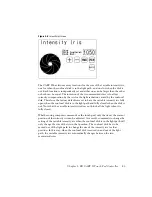
Страница 42: ...Wheel Screen with Calibration Function Activated Intensity Iris Screen The Intensity Iris Screen is displayed when the light bulb graphic Variable Intensity Iris button on the Main Screen is pressed This screen is used to control the variable intensity iris which is mounted immediately after the shutter in the light path The Intensity Iris Screen will differ depending on the location of the confoc...

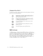
Страница 43: ...iris fully open when the confocal disk is in the light path and fully closed when the disk is out Note that the variable intensity iris does not block all the light when it is fully closed Whether using computer commands or the touch pad only the size at the current position of the intensity iris can be adjusted As a result commands to change the setting of the variable intensity iris when the con...

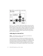
Страница 44: ...lows manual control of the FRAP iris which creates a rectangular aperture on the image to enable controlled photo bleaching of the sample An example of the FRAP Iris Screen is shown in Figure 3 7 The plus button increments the variable intensity iris size by 10 Holding the plus button down rapidly increases the size by 10 s all the way to the maximum of 1050 The minus button decrements the variabl...

Страница 45: ...the center of the iris graphic for a few seconds The calibration function is activated when a second set of and buttons appear directly beneath the original ones as in Figure 3 8 The calibration function does not effect the size of the FRAP iris but rather the position of the iris in the light path Moving the confocal disk into the light path while the calibration function is activated changes the...

Страница 46: ...sed with the filter configurations shipped with the unit Selecting preset 1 Blue moves all three filter wheels to Position 1 Preset 2 Green moves all three filter wheels to Position 2 Preset 3 Red moves all three filter wheels to Position 3 Preset 4 FRAP is unique because the excitation wheel moves to Position 5 the dichroic wheel moves to Position 5 and the emission wheel doesn t move at all The ...

Страница 47: ... disk in the light path can be calibrated using the touch pad Because calibrating the devices within the CARV II can adversely affect the optical performance only qualified personnel should perform these procedures Calibrating the Prism NOTICE Once the calibration for the prism has been changed there is no way to restore the factory setting without optically aligning the instrument therefore use c...

Страница 48: ... function To hide the calibration buttons without leaving the Main Screen press the camera button Calibrating the Confocal Disk NOTICE Users should never attempt to calibrate the confocal disk these instructions are for trained technicians only The confocal disk position can be adjusted in the light path in much the same way as the prism above However several steps must be performed before the cal...

Страница 49: ...justments to the confocal disk can also cause noise from the servo motor and must be done carefully Calibrating the Filter Wheels Because the positioning of the filters is so critical to an optimized light path the calibration of the filter wheels is done in a different manner Like the other calibration equipped devices in the CARV II each position of each filter wheel has its calibration value st...

Страница 50: ... will need to be re calibrated Instructions for activating the calibration function for the filter wheels and a screen shot for each screen can be found in the Eight Position Filter Wheel Screens on page 39 or the Dichroic Wheel Screen on page 41 Notice that the calibrated value for the active position on the wheel is displayed when the calibration function is activated These values can be read fo...

Страница 51: ...51 4 BD CARV II Command Sets The following topics are covered in this chapter Software Communication Devices Command Conventions Command Formats ...

Страница 52: ...that joins the touch screen assembly and the main CARV II unit need not be present in order for the software to communicate with the touch screen relevant commands will have a reaction on the touch screen display however no actual movement occurs in the main unit without the cable Regardless of the controlling application the settings for the COM port used to connect to the CARV II are as follows ...

Страница 53: ...y characters sent on the serial port until it receives a CR 2 For simultaneous motion from more than one device commands can be chained together with only one CR at the end For example the excitation wheel can be moved to Position 2 and the shutter opened with A2S1 CR or A2 S1 CR DEVICE DEVICE ID Valid Positions Homes To Excitation Filter Wheel A 1 2 3 4 5 6 7 8 Position 1 Emission Filter Wheel B ...

Страница 54: ...may not actually be simultaneous The processor handles the individual commands sequentially and sets each device in motion in that order Faster devices or devices that make a shorter move may complete motion before a slower device even starts motion For the most time efficient coordination of moves slower devices or ones making a longer move should appear in the compound command first 3 When the e...

Страница 55: ...er and ignore all touch actions but the display will update as commands are sent from the host Command Formats In the following command descriptions the Format describes how the command should look as an individual command Individual commands can be appended with other commands to make a compound command as outlined in the command conventions above Parameters describe any characters that must acco...

Страница 56: ...sent to host 1 responses sent to host Return Value If active 0 no response If active 1 R1 CR Examples R0 CR J R1 CR J R1 CR All commands generate a response to the host Format H CR Parameters none Return Value HA1B1C1D0P0N0S0I1050V450 CR Examples H CR J HA1B1C1D0P0N0S0I1050V450 CR All devices are in their Home Positions as reported See Table 4 1 for more information Format device ID position CR Pa...

Страница 57: ... directed to the binocs Format S source CR Parameters source X External trigger source BNC camera sync cable I Internal trigger source Return Value S source CR Examples SX CR JSX CR The shutter trigger source is now set as external Format F device ID position value CR Parameters device ID ID assigned to a filter wheel see Table 4 1 position Position of device that receives the value For example A ...

Страница 58: ...at f CR Parameters device ID ID assigned to device see Table 4 1 position Position of device that is calibrated to value For example A 1 H 8 value Calibrated value for position Return Value F device ID position value position value CR device ID position value position value CR device ID position value position value CR Examples f CR J fA A450B575C708D825E893F956G1050 CR B A450B582C715D808E895F966G...

Страница 59: ...where the device actually is Incorrect reporting is probably a sign of hardware malfunction v Read Version of Firmware R Device ID and position of Confocal Disk Motor S Device ID and state of Shutter I Device ID and position of FRAP Iris V Device ID and position of Variable Intensity Iris Return Value q A B C D P R S I CR Examples q CR J qA8 B8 C5 D1 P0 N1 S0 I910 CR Format r deviceID CR Parameter...

Страница 60: ...60 BD CARV II Installation and User s Guide Examples v CR J vVer 1 02 CR The touch screen firmware version is reported as Ver 1 02 ...

Страница 61: ... components 14 computer control 35 confocal disk icon 38 confocal head mounting to microscope 29 D DB 25 cable 34 DB 9 connector 34 device IDs 52 positions 52 dichroic filter wheel 21 Dichroic Wheel Screen 41 DIN connector 34 E Eight position Filter Wheel Screens 39 emission filter wheel 21 Emission Wheel Screen 39 excitation filter wheel 22 Excitation Wheel Screen 39 eyepieces 11 27 F filter desc...

Отзывы: