3
www.bdsensors.de
ASM 400
1. General
1.1 Information on the intended use
•
The display and switching unit ASM 400 can be integrated in any transmitter or trans-
ducer with 4 … 20 mA / 2-wire or 0 … 10 V / 3-wire analogue output. With the ASM 400
a digital display and up to 2 contacts are available.
•
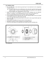
Mounting the unit into different devices is very simple. A hole and up to 2 grooves have
to be machined in a designated housing.
•
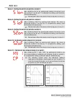
The display can be programmed via two push-buttons. The following parameters can be
adjusted: scaling, decimal point, damping, and limit contact (optional). Those parameters
are being stored in an EEPROM and, thus, kept also in case of a power breakdown.
•
The device shall be used according to the area of application specified above!
•
No liability is assumed and warranty claims are excluded in case of improper application,
modification of or damage to the device.
1.2 Target group
This operating manual is intended for qualified technical personnel.
The display and switching unit ASM 400 has been exclusively designed for qualified companies
that have a large know how in the final assembly of fine mechanical and electrical devices as
well as bonding, joining and soldering technologies.
1.3 Symbols used
: Caution
: Note
1.4 Safety information
The following notes must be observed to avoid hazards for the operator and his environ-
ment:
The device may only be installed, used and serviced by persons who are familiar with
this operating manual!
Applicable regulations regarding occupational safety, accident prevention and national
installation standards must be complied with!
The product must only be used within the specifications! (Compare the technical
data under "12. Technical Data".)
The electronical assembly group in the ASM 400 is equipped with EMC compo-
nents. The manufacturer of the total appliance must ensure CE conformity.
Mount the device in the currentless condition!
Содержание ASM 400
Страница 18: ...ASM 400 Dimensions...
Страница 19: ...19 www bdsensors de ASM 400...


