background image


                              MX310HD User’s Manual 


45

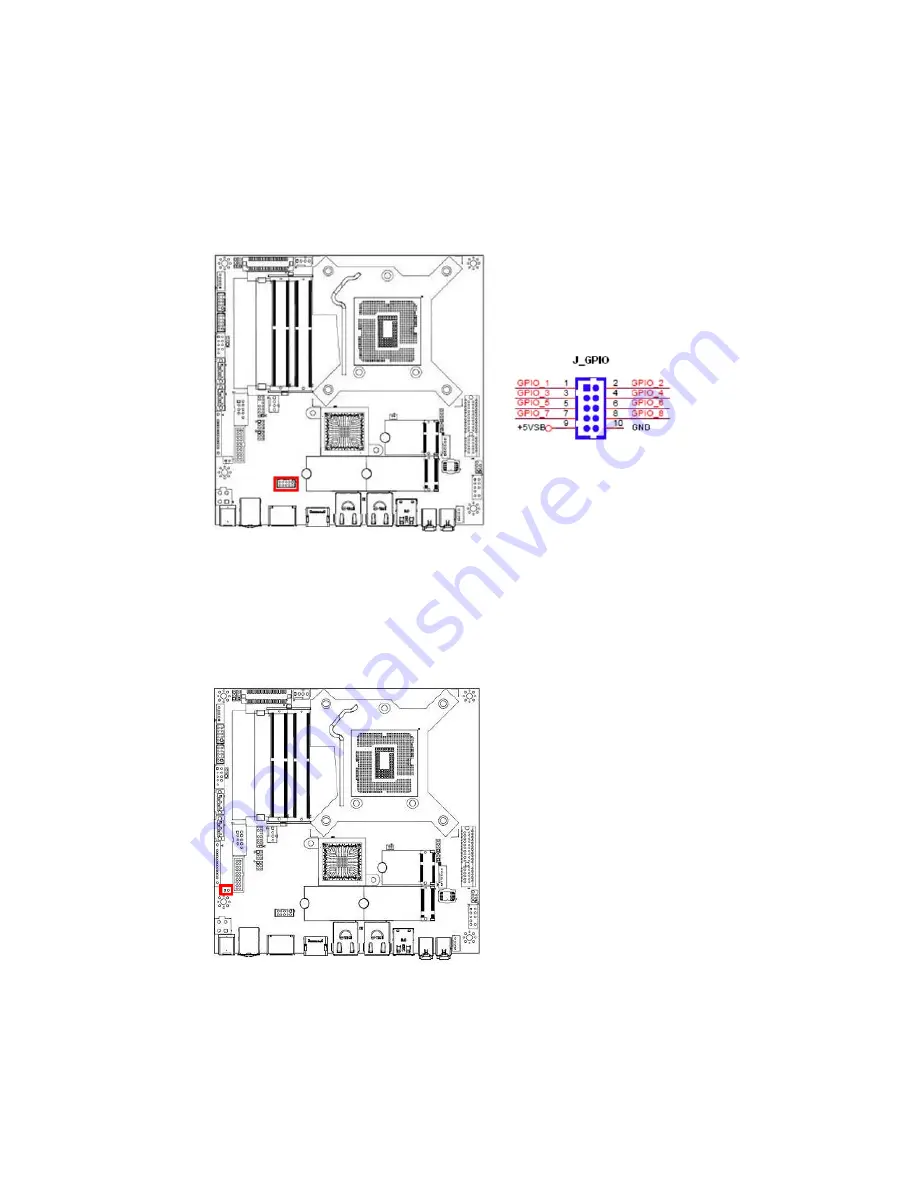
1.9.15   GPIO Header:  J_GPIO 


     This header provides 8-bit general purpose I/O (GPIO) connections to external device. 


    Customer can write their own monitoring program to monitor the status of external device 


  connected with this header. 


1.9.16   Chassis Intrusion Header:    J_CHASSIS 


    This 2-pins header provides chassis intrusion warning connection. 


Содержание MX310HD

Страница 1: ...310HD Intel H310 PCH Supports Coffee Lake 8th Gen Coffee Lake Refresh 9th Gen i7 i5 i3 Pentium processors Supports up to 6 Cores and up to TDP 65W type processors only Mini iTX Motherboard User s Manu...

Страница 2: ...AND USED IN ACCORDANCE WITH THE INSTRUCTION MANUAL MAY CAUSE HARMFUL INTERFERENCE TO RADIO COMMUNICATIONS OPERATION OF THIS EQUIPMENT IN A RESIDENTIAL AREA IS LIKELY TO CAUSE HARMFUL INTERFERENCE IN...

Страница 3: ...rch makes no representation or warranty that such application will be suitable for the specified use without further testing or modification Life Support Policy BCM Advanced Research PRODUCTS ARE NOT...

Страница 4: ...answers in your product documentation These answers are normally a lot more detailed than the ones we can give over the phone So please consult the user s manual first To receive the latest version of...

Страница 5: ...ervice time and freight Please consult your dealer for more details If you think you have a defective product follow these steps 1 Collect all the information about the problem encountered For example...

Страница 6: ...o inform us of these please contact our Customer Service department with the relevant details Safety Precautions Warning Always completely disconnect the power cord from your chassis whenever you work...

Страница 7: ...and Fan 29 1 6 System Memroy 31 1 6 1 Overview 31 1 6 2 Memory Configurations 32 1 6 3 Installing the DDR4 SODIMM 33 1 6 4 Removing the DDR4 SODIMM 34 1 7 Power Supply 35 1 7 1 12V DC In Power Connect...

Страница 8: ...LVDS Brightness Mode Select JP2 48 1 10 6 Clear CMOS Jumper JP3 49 1 11 The Expansion Slots 50 1 11 1 Installation of Expansion Card 50 1 11 2 Setup An Expansion Card 50 1 11 3 PCIe x4 Slot J_PCIE4X 5...

Страница 9: ...3 7 5 4 WatchDog TimeOut Value 61 3 7 5 5 Chassis Opened Warning 61 3 7 5 6 ErP EuP S5 Support 61 3 7 6 HW Monitor 62 3 7 6 1 Smart Fan 62 3 7 6 1 1 Smart Fan Function 62 3 7 6 1 2 Smart Fan Mode Conf...

Страница 10: ...xpress Configuration 67 3 8 2 2 SATA And RST Configuration 67 3 8 2 3 USB Configuration 67 3 8 2 4 HD Audio Configuration 67 3 8 2 5 LAN1 Controller 67 3 8 2 6 Wake on LAN1 from S3 S4 S5 67 3 8 2 7 LA...

Страница 11: ...0HD User s Manual 11 3 11 4 Load Optimized Default 71 Chapter 4 Application Note 72 4 1 Windows 10 Drivers Installation 72 4 2 Display through PCIe video card installed on J_PCIEX4 slot 73 4 3 PXE Boo...

Страница 12: ...920x1200 SATA 2 x SATA III connectors 1 x SATA power connector M 2 1x M 2 Type M 2242 2280 Slot with USB PCIe x2 SATA III 1 x M 2 Type E 2230 with USB PCIe x1 USB 4 x USB 2 0 ports 2 1x Header 2 Rear...

Страница 13: ...onnector SPI 1 x Header I2S 1 x Header I2C 1 x Header GPIO 1 x Header Chassis Intrusion 1 x Header Onboard Jumpers COM Port Ring In Power Select 2 x Headers provides Selection of Ring In or 12V or 5V...

Страница 14: ...l 14 Power Connector 1 x 4 pin ATX Connector 12V 24V Wide Range Max current 8A 1 x DC Connector 12V 24V Wide Range DC In For 12V AC adapter Max current 8A For 19V AC adapter Max current 8A Form Factor...

Страница 15: ...and latest technologies making it another line of BCM long life mainboards Before you start installing the mainboard and hardware devices on it check the items in your package with the list below If...

Страница 16: ...l object such as the power supply case before handling components to avoid damaging them due to static electricity Hold components by the edges to avoid touching the ICs on them Whenever you uninstall...

Страница 17: ...nto it Make sure to unplug the power cord before installing or removing the mainboard Failure to do so can cause you physical injury and damage mainboard components 1 4 1 Mounting Holes Place the scre...

Страница 18: ...MX310HD User s Manual 18 1 4 2 Mainboard Layout...

Страница 19: ...PCIE4X PCIe x4 slot 1 4 3 2 Internal Jumpers Label Function Note Page JP1 LVDS PWM Backlight Power Select 3 3V default 5V 1 x 3 header pitch 2 00mm JP2 LVDS Brightness Mode Select PWM Mode default DC...

Страница 20: ...SB3 12 USB3 0 Port 1 2 2 x 10 box header pitch 2 00mm J_FR PANEL System Panel Connector 2 x 5 header pitch 2 54mm 32 J_FR AUDIO Front Panel Audio Connector 2 x 5 header pitch 2 54mm 30 J_AMP OUT Ampli...

Страница 21: ...r 12V AC adapter Max current 8A For 19V AC adapter Max current 8A AC adapter connector dimension Inner Diameter 2 5 0 1mm Outer Diameter 5 5 0 1mm 25 J_USB2 89 USB2 0 Ports J_DP Display Port 25 J_HDMI...

Страница 22: ...it related Keep the PnP cap after installing the mainboard BCM will process Return Merchandise Authorization RMA requests only if the mainboard comes with the cap installed on the LGA1151 socket The p...

Страница 23: ...n 1 Locate the CPU socket LGA1151 Socket on the mainboard 2 Unlatch the CPU Socket Lever by pressing the lever down and move it away from the main structure of the socket To prevent damage to the sock...

Страница 24: ...it black color a k a CPU Socket Cover or PnP cap in order to protect the socket pins from damage If you are going to install a CPU remove the plastic protection cap away from the CPU socket by liftin...

Страница 25: ...two Socket Alignment keys on the CPU socket as well Line up the two CPU notches with the Socket Alignment Keys on the socket and insert the CPU into the CPU socket slowly 6 Visually inspect if the CP...

Страница 26: ...nt Plates are sliding underneath the Shoulder Screw Cap 8 Secure the CPU Socket Cover by keep pressing down the CPU Socket Lever and move it toward and underneath the Load Plate Tab The CPU fits in on...

Страница 27: ...CPU heatsink and fan assembly is designed to withstand the TDP Thermal Dissipation Power specified by Intel specification of corresponding CPU that you are going to install b You have properly applied...

Страница 28: ...ble to the connector on the mainboard labeled J_CPU FAN A Do not forget to connect the CPU fan connector Insufficient air flow inside the system chassis may damage the mainboard components Hardware mo...

Страница 29: ...an To uninstall the CPU heatsink and fan 1 Disconnect the CPU fan cable from the connector on the mainboard 2 Rotate each fastener counterclockwise 3 Pull up two fasteners at a time in a diagonal sequ...

Страница 30: ...ser s Manual 30 4 Rotate each fastener clockwise to ensure correct orientation when reinstalling The narrow end of the groove should point outward after resetting The photo shows the groove shaded for...

Страница 31: ...ta rate fourth generation synchronous dynamic random access memory is a type of synchronous dynamic random access memory SDRAM with a high bandwidth double data rate interface The primary advantages o...

Страница 32: ...ximum slot When there is only one DDR4 memory module being installed it is recommended to install it on J_SODIMM1 slot When two SODIMMs being populated only install identical same type same size same...

Страница 33: ...ch key on the SODIMM module with the rib on the slot 4 Firmly press the SODIMM module into the socket which will be snapped into the mounting notch automatically Do not force the SODIMM module in with...

Страница 34: ...hese steps to remove a SODIMM 1 Press the two ejector tables on the slot outward simultaneously 2 Remove the SODIMM module from the socket Hold the SODIMM module gently when pressing the ejector tabs...

Страница 35: ...version and provides a power of 96W Maximum Current Limit 8A on this header 2 Use of a PSU with adequate power output is recommended when configuring a system with more power consuming devices The sys...

Страница 36: ...ter Diameter 5 5 0 1mm 2 J_USB2 89 USB2 0 Ports The USB2 0 Port Connectors 3 J_DP Display Port The Display Port Connector 4 J_HDMI HDMI Port The HDMI Port Connector 5 J_LAN1 Gigabit LAN RJ 45 Connecto...

Страница 37: ...for the LAN port LED indications ACT Link LED Speed LED Status Description Status Description OFF No link OFF 10Mbps connection Orange Linked Green 100Mbps connection Blinking Data activity Orange 1Gb...

Страница 38: ...front panel switches and LEDs The J_FR PANEL connector is compliant with Intel Front Panel I O Connectivity Design Guide 1 9 2 Serial ATA 3 0 Connectors J_SATA3 1 J_SATA3 2 SATA ports J_SATA3 1 and J...

Страница 39: ...J_SATA3 2 1 9 4 CPU System Fan Connectors J_CPU FAN J_SYS FAN The 4 pins fan power connector supports system cooling fan with 12V In order to take the advantage of System Hardware Monitor and Smartfan...

Страница 40: ...hassis mounted front panel audio I O module that supports HD Audio standard Connect one end of the front panel audio I O module cable to this connector 1 9 6 Amplifier Connector J_AMP OUT This header...

Страница 41: ...USB3 0 cable required 1 9 8 Front USB2 0 Headers J_USB2 56 This header provides two USB2 0 connections An USB2 0 cable required Be sure the pins of USB 5V and GND signals are connected to the correspo...

Страница 42: ...Port Connector J_COM1 J_COM2 These headers provide serial connections on COM1 COM2 respectively 1 9 10 LVDS Header J_LVDS This header provides connection to LVDS type panels 800x600 18 bit Single cha...

Страница 43: ...er s Manual 43 1 9 11 LVDS Panel Backlight Connector J_BACKLIGHT This header provides connection for LVDS panel backlight control connections 1 9 12 SPI Header J_SPI This header provides SPI signal co...

Страница 44: ...MX310HD User s Manual 44 1 9 13 I2S Header J_I2S This header provides I2S signal connections 1 9 14 I2C Header J_I2C This header provides I2C signal connections...

Страница 45: ...general purpose I O GPIO connections to external device Customer can write their own monitoring program to monitor the status of external device connected with this header 1 9 16 Chassis Intrusion Hea...

Страница 46: ...or AT mode When the system is set in AT mode the system power on off will be controlled directly by the power switch on the power supply And some of the power saving modes will not function as ATX mod...

Страница 47: ...V Select JP5 This header provides the options of selecting the COM port function as Ring in default or 5V or 12V 1 10 4 COM2 Ring In 12V 5V Select JP6 This header provides the options of selecting the...

Страница 48: ...cting the connected LVDS panel brightness mode either in PWM mode default or DC mode The mode selected is depending on the type of LVDS panel inverter used NOTE It also requires to make the same setti...

Страница 49: ...n pin location 1 and 2 To clear the CMOS disconnect all power connections to MX310HD first then set the JP3 jumper to pin location 2 and 3 for at least 30 seconds while the system is disconnected from...

Страница 50: ...emove the chassis cover if the mainboard is installed in a chassis 3 Remove the expansion slot bracket from the chassis on the slot that you intend to use Keep the screw for later use 4 Align the card...

Страница 51: ...MX310HD User s Manual 51 1 11 3 PCIe x4 Slot J_PCIE4X The PCIe x4 slot supports PCIe x1 PCIe x4 cards e g PCIe LAN cards or some of the PCIe x16 video cards...

Страница 52: ...r s Manual 52 1 11 4 M 2 Sockets 1 11 4 1 M 2 Socket M Key J_M2M The J_M2M socket supports M Key SATA type SSDs in 2242 or 2280 1 11 4 2 M 2 Socket E Key J_M2E The J_M2E socket supports E Key WIFI car...

Страница 53: ...en orange and green after the system is on If it complies with green standards or if it is has a power standby feature The system will then run power on test While the test are running the BIOS will a...

Страница 54: ...rst bootable device from this menu 8 Power off your computer You must first exit or shut down your operating system before switch off the power switch If you use Windows Operating Systems click Start...

Страница 55: ...gnostic test called POST power on self test for all the necessary hardware it detects the entire hardware device and configures the parameters of the hardware synchronization Only when these tasks are...

Страница 56: ...an make changes to You can use the arrow keys to select the item The on line description of the highlighted setup function is displayed at the bottom of the screen Sub Menu If you find a right pointer...

Страница 57: ...ng screen appears The BIOS menu screen displays the items that allow user to make changes to the system configuration To access the menu items press the up down right left arrow key on the keyboard un...

Страница 58: ...nu gives user an overview of the general system specifications such as time date etc BIOS Information Displays the auto detected BIOS information System Date The date format is Date Month Day Year Sys...

Страница 59: ...Processor Cores Number of cores to enable in each processor package 3 7 1 3 Hyper Threading Enabled for Windows and Linux OS optimized for Hyper Threading Technology Disabled for other OS OS not optim...

Страница 60: ...g replaced 3 Hard Drive failure Note 1 Once BIOS option Load Optimized Default is loaded the Trusted Computing option under the BIOS menu will be disappeared which is normal Just save and exit the BIO...

Страница 61: ...utes or seconds 3 7 5 4 WatchDog TimeOut Value Fill WatchDog TimeOut value 0 means disabled 3 7 5 5 Chassis Opened Warning Enable disable the chassis intrusion feature It requires 2 wires connection f...

Страница 62: ...Smart Fan function page 3 7 6 1 1 Smart Fan Function Smart Fan function enable disable 3 7 6 1 2 Smart Fan Mode Configuration Setup the desired target temperatures for fans connected to fan headers J...

Страница 63: ...s legacy support if no USB devices are connected Disabled Will keep USB devices available only for EFI applications 3 7 8 2 XHCI Hand off This is a workaround for OSes without XHCI hand off support Th...

Страница 64: ...LAN2 1 Enter BIOS option BIOS advanced Network Stack Configuration set Network Stack set to Enabled 2 Set IPv4 PXE Support to Enabled 3 Save and Exit BIOS 4 Enter BIOS menu after reboot Enter Boot UEF...

Страница 65: ...r s Manual 65 3 7 10 CSM Configuration Enable Disable option ROM execution settings etc 3 7 10 1 CSM Support Enable Disable CSM Support 3 7 10 2 Boot Option Filter This option controls Legacy UEFI ROM...

Страница 66: ...elated settings 3 8 1 2 1 Primary Display Select which of IGFX Internal Graphic from CPU PCIE The PCIe graphic card installed on J_PCIE4X slot 3 8 1 2 2 Internal Graphics Keep IGFX enabled based on th...

Страница 67: ...Express Configuration PCI Express designations for onboard M 2 sockets J_M2M J_M2E and LAN1 LAN2 3 8 2 2 SATA And RST Configuration SATA Device Options Settings 3 8 2 3 USB Configuration USB Configur...

Страница 68: ...r Loss Specify what state to go to when power is re applied after a power failure G3 state 3 8 2 9 GPIO Group Control Configure the digital GPIO pins 3 8 2 10 Amplifier GAIN db Select Amplifier GAIN v...

Страница 69: ...MX310HD User s Manual 69 3 9 Security Setup the administrator or user passwords and secure boot related settings...

Страница 70: ...ock State Select the keyboard NumLock state 3 10 3 Quiet Boot Enable or disable quiet boot option 3 10 4 Boot Mode Automatically set CSM s item to Legacy or UEFI 3 10 5 FIXED BOOT ORDER Priorities Set...

Страница 71: ...nd Exit Exit system setup after saving the changes 3 11 2 Discard Changes and Exit Exit system setup without saving any changes 3 11 3 Save Changes and Reset Reset the system after saving the changes...

Страница 72: ...ate Win10 to the latest version through Windows Update by connecting Ethernet cable to MX310HD onboard i211 LAN Located next to the rear I O USB3 0 ports blue color USB ports 2 Install Intel LAN Drive...

Страница 73: ...s video output to monitor B 8 Boot the system into Windows 10 desktop 9 Check under Device Manager and make sure the installed PCIe video card is being detected NOTE If the installed PCIe video card i...

Страница 74: ...iguration Enable Network Stack 3 Set Ipv4 PXE Support to Enabled 4 Save and Exit BIOS 5 Reboot the system 6 Enter BIOS option Boot UEFI Network Drive BBS Priorities choose the desired boot LAN The cho...

Отзывы: