3
10777 - GB-CZ-HU-PL-RO-RU - 0 - 04 / 07
1
DESCRIPTION
This equipment complies with the following EC Directives:
- 73/23
Low Voltage
- 89/336
Electromagnetic compatibility
- 89/392
Machines
- 97/23
Pressure vessels (Article 3.3).
The burner should be fitted to the front of the boiler and
comprises:
- the burner head, inside the combustion chamber
- the air and fuel distribution system, outside the boiler
under a cover
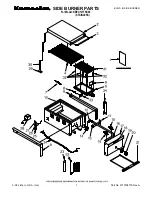
The main parts of the burner are listed in the following
table and identified on the photograph below (without
cover).
Burner units are delivered in a package containing:
- a burner.
- pack of fittings comprising:
. fixing flange
. gasket
. nuts, bolts and washers
. nozzle
. wrench
. two hoses
. two nipples
. one electric connector
- documentation pack (instructions, boiler room plate,
warranty card, quality monitoring card).
This burner was designed to operate with domestic
fuel with viscosity at 20
°
C of between 2 and 7.5 cSt.
It is known that fuel viscosity greatly varies at low
temperatures. It is recommended that the tank and fuel
inlet and return pipes are protected against the cold.
Fuel of 5 cSt viscosity at 20
°
C switches to 10 cSt
viscosity at 0
°
and 15 cSt viscosity at -10
°
. Nozzle
spraying and flow are then fully changed and there is
a risk of clogging and breakdown.
V
T
H
D
A
B
L
C
S
J
U
G
I1
W
I
O
R
M
K
Q
N
P
F
E
1.2
One stage burner
Item
Description
Item
Description
A
Mounting screw for rear casing (4)
L
Line position setting screw (stabilizer / flare)
B
Photoconductive cell
M
Oil vacuum connector
C
Head air pressure connector
N
Oil suction
D
Programming unit
O
Intake
E
Programming unit base + connectors
P
Oil tank return
F
Electric igniter
Q
Oil pressure setting screw
G
Cover support square and maintenance position
R
Pump filter
H
Oil solenoid valve
S
Electric motor starter condenser
I
Maintenance position housing N° 1
T
Electric motor
I1
Maintenance position housing N°2
U
Intake locking screw
J
Oil pump
V
Air flap setting button
K
Oil pressure connector
W
Protective mesh


