background image

DVS Series

Installation and Operating Manual

14

SETUP MENU

The 

Setup 

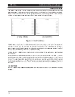
menu is displayed when the menu system is entered:

(For the DVS24A and DVS28A)

KEY LOCK                OFF
TITLES
DWELL

ALARMS
EXIT

Ver x.x

DEFAULTS

SETUP

(For the DVS14 and DVS18)

KEY LOCK                OFF
TITLES
DWELL
DEFAULTS
EXIT

Ver x.x

SETUP

Figure 10 - Setup Menu

Key Lock

Select this option to turn the keyboard lock function 

ON 

and 

OFF

. If the keyboard is locked,

an operator will be unable to switch from camera to camera or change modes. The only

buttons that will have any effect will be the 

Number 1

 button and 

Auto 

button, which when

held together will open the menu system. The keyboard lock can then be turned off if

required.

Titles

Select this option to enter the 

Titles 

sub-menu. This sub-menu is used to edit the title for

each camera input that is connected to the switcher. When the images from a camera input

are shown on-screen, the appropriate title is also shown so that the source of the images is

easily identifiable. For more details, see page 15.

Dwell

Select this option to enter the 

Dwell 

sub-menu. This sub-menu is used to specify the dwell

time for each individual camera when a sequence is performed on the main monitor.
If the switcher is a DVS24A or DVS28A, this sub-menu is also used to set the global dwell

time, which is applied to every camera in a sequence on the second monitor.
For more details on this menu, see page 16.

Defaults

Select this option to restore the original factory settings to the switcher. When this option is

selected, the action must be either confirmed by pressing the 

OK 

button, or cancelled by

pressing the 


button.

Alarms

This option is only available on the DVS24A and DVS28A switchers. It is used to enter the

Alarms 

sub-menu. This sub-menu is used to specify various options and settings concerning

any alarm inputs and outputs that are connected to the switcher. For more details, see

page 17.

Exit

Select this option to exit the menu system. Any changes made to the settings while in the

menu system are automatically saved.

Содержание DVS14

Страница 1: ...DVS Series Desktop Video Switchers Installation and Operating Manual Please read these instructions before installing your equipment...

Страница 2: ...ion and Operating Manual 2 IMPORTANT The first few pages of these instructions contain important information on safety and product conformity Please read and ensure that you understand this informatio...

Страница 3: ...eclaration of Conformance 4 Unpacking 4 Overview 5 Rear Panel Connections 7 Connecting the Switcher 8 Alarm I O Connector 9 DVS14 and DVS18 Operation 10 DVS24A and DVS28A Operation 11 The On Screen Me...

Страница 4: ...esidential commercial or light industrial EMC environment Refer to Baxall Limited before using the product is medical and or intrinsically safe applications or in an industrial EMC environment This pr...

Страница 5: ...efinable camera titles Aside from these common features DVS Series switchers fall into two groups those with alarm functionality and those without DVS14 and DVS18 The DVS14 can be connected to four ca...

Страница 6: ...uired Sequences can also be run simultaneously on both monitors Both the DVS24A and DVS28Aunits have alarm functionality The alarm inputs are designed so that when an alarm is triggered the main monit...

Страница 7: ...s Video Output Power Connector Power supply cable strain relief point DVS18 Video Inputs Video Outputs Alarm I O Connector Power Connector Power supply cable strain relief point DVS24A Video Inputs Vi...

Страница 8: ...nputs DVS24A or DVS28A connect the Alarms I O Connector 5 Connect the jack plug from the 12V DC power supply into the jack socket marked 12V DC Use the power supply cable strain relief point to preven...

Страница 9: ...GROUND Pin 1 Figure 5 Alarm Input Connections Alarm Outputs An internal relay is provided so that the DVS can be connected to other equipment The behaviour of this relay can be programmed using the m...

Страница 10: ...sing the button for a video source that doesn t have a camera connected to it will display a NO VIDEO message until another camera is selected Auto Mode To operate the unit in Auto mode press the Auto...

Страница 11: ...n t have a camera connected to it will display a NO VIDEO message until another camera is selected The unit can also be used to manually select and display cameras on the spot monitor To do this hold...

Страница 12: ...uto mode press any of the input selection buttons Note The DVS24A and DVS28A are fitted with alarm inputs The operation of the switchers when in alarm condition depends largely on the settings in the...

Страница 13: ...buttons The and buttons are then used to change the selected parameter for that menu item A menu item with no parameters indicates that a sub menu exists To reveal the sub menu highlight the menu item...

Страница 14: ...is also shown so that the source of the images is easily identifiable For more details see page 15 Dwell Select this option to enter the Dwell sub menu This sub menu is used to specify the dwell time...

Страница 15: ...be selected 2 Using the and buttons highlight the character in the camera title that is to be changed 3 Press the OK button The Letter Selection screen is displayed 4 Using the and buttons navigate th...

Страница 16: ...a input and each of these fields indicates a dwell time in seconds To alter the dwell time of an individual camera input use the and buttons to select the required camera input and use the and buttons...

Страница 17: ...put is no longer current When using this option there is no need for an alarm input to be acknowledged and cleared by an operator Ack Acknowledge An alarm input must be cleared by pressing the button...

Страница 18: ...ore the alarm was activated OUTPUT This item is used to specify how the relay contact a set of three pins in the Alarms I O Connector that controls the alarm output works when an alarm input is trigge...

Страница 19: ...ad woodscrews 2 Fit screw A leaving it protruding from the surface by approximately 6 5mm 3 Locate the keyhole shaped slot on the underside of the DVS unit over the head of the screw Slide the DVS unt...

Страница 20: ...m Dwell time is individually adjustable between 1 and 60 seconds on main monitor and globally adjustable between 5 and 60 seconds on second monitor 12 character camera title for each input individuall...

Страница 21: ...1 75 5mm 75 5mm 95mm Max Hole Size 3 8mm Max Hole Size 3 8mm Max Hole Size 3 8mm ORIGINAL SCALE 1 1 It is imperative that the dimensions on the supplied template are checked to ensure that the diagram...

Страница 22: ...DVS Series Installation and Operating Manual 22...

Страница 23: ...Installation and Operating Manual DVS Series 23...

Страница 24: ...HB DVS 3 Baxall Limited Stockport England Visit our Web site http www baxall com Baxall Limited reserve the right to make changes to the product and specification of the product without prior notice t...

Отзывы: