Installation
Instruction handbook Mains filters
BFN
Document No.: 5.09010.03
51
7
m
A minimum distance of 20 cm should be kept between the conductors at a parallel in-
stallation of signal- and control cables and the power cables.
m
The distance between cables with very high interference potential and with cables on
the mains side of the mains filters should be at least 30 cm.
m
Try to cross cables with different EMC-categories in a 90°-angle.
m
The conductors of each core pair must be twisted at symmetric signal transmission (for
example differential amplifier inputs for the speed value). The core pairs must be twist-
ed with the other core pairs.
m
Ground connection converter/ground plate should be as short as possible (< 30 cm). It
must be finely stranded. Use great cross-sections (recommended > 10 mm).
m
Connect the PE-connection on the load-side of the filter with low impedance to the
mounting plate. A zinc-plated sheet metal bracket or a HF-ground band would be per-
fect.
m
There should be a distance of at least 20 cm to the power converter and its wirings for
parts, which cause interferences (for example contactors, transformers, chokes) and
for susceptible parts (for example
Ps, bus systems).
m
Avoid reserve loops at long cables.
m
Ground reserve cables at both ends (additional screening effect, avoid capacitively
coupled, dangerous accessible voltages).
Grounding
m
In order to reduce the influence of high-frequency interferences, which were generated
when operating the power converter, the basic star-grounding does not comply to
EMC. A reference surface is required to connect the devices large-surfaced with the
potential to ground (for example a metallic bright mounting plate and cabinet parts)
m
Mount the power converter with its mains filters and the bonded face-to-face screen
contactor of the motor cable to the same reference surface.
m
All grounding conductors and screens should be led directly above ground, so that no
ground loops occur.
m
Ground the controller-reference potential of the power converter. Connect with a great
cross-section and a short cable (< 30 cm).
m
Remove insulating layers (varnish, adhesive) from the ground connections. Use ser-
rated washers (DIN 6798) to reach the surface. This way a durable conductive contact
is achieved. . In order to prevent corrosion of ground connection, select suitable metal
pairs (observe electrolytic series of metals). Keep the conductive electrolytics from the
connection by using a protective coating (for example grease)
m
The screens must be bonded at both ends face-to-face and well conductive to ground.
This way the effects of magnetic or highly-frequent interference fields can be attenuat-
ed. The receiver should be connected isolated, the transmitter should be connected
capacitive, if problems with ground loops occur (for example double grounding of set
value cable screening).
m
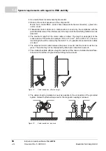
When leading external cable screens through walls, contact the different EMC-ranges
separated from one another.
Cables, which are led through walls of screening cabinets without special precautions
(for example filtering), can influence the screening effect of these cabinets. Therefore,
also connect the cable screenings with well conductivity at the cabinet’s outlet with the
screening wall.

