background image


Installation and Maintenance Manual: RLVAC


Published February 2022 

Rev. B 


9


List of Tables 

Table 1: Reference Documents ............................................................................................................... 9 
Table 2: Belt Hot Splicing Tools ............................................................................................................. 25 
Table 3: Belt Hot Pressing Parameters .................................................................................................. 27 
Table 4: Return Roller Positions for Intermediate Beds .......................................................................... 31 
Table 5: Pneumatic Takeup Pressure Settings ....................................................................................... 39 
Table 6: Recommended Preventative Maintenance Schedule ................................................................ 43 
Table 7: Fastener Standard Torque Values ............................................................................................ 44 
Table 8: Troubleshooting Guide ............................................................................................................. 59 
Table 9: Standard Gearmotors with 1.250in Output ................................................................................ 62 
Table 10: Standard Gearmotors with 1.500in Output .............................................................................. 63 
Table 11: RLVAC General Arrangement BOM ....................................................................................... 64 

 
Reference Documents 

Table 1: Reference Documents 


MANUFACTURER 

MANUAL 

Bastian


Solutions


Conveyor Director AC User Manual 

Bastian Solutions  

Side Cover and Guiderail Installation Manual 

Bastian Solutions 

Support Installation Manual 

Bastian Solutions 

RLCAC Installation and Maintenance Manual 

Bastian Solutions 

RLSAC Installation and Maintenance Manual 

Habasit Holding 

AG 

Habasit Fabric Conveyor Belts Installation and Maintenance Guide (6040) 

ABB Motors and 

Mechanical Inc  

Dodge Quantis RHB Installation and Maintenance Instructions (499322) 

ABB Motors and 

Mechanical Inc 

Instruction Manual for DODGE® Setscrew, Eccentric Collar, D-Lok, H-E Series, 

E-Z Kleen, Ultra Kleen and Food Safe Mounted Ball Bearings (MN3016) 

ProCal 

Innovations, LLC 

(PCI) 

INSTALLATION INSTRUCTIONS: XT®, QD®, HE & TAPERLOCK® BUSHINGS 

(31905) 

Содержание RLVAC

Страница 1: ...Installation and Maintenance Manual Model RLVAC Effective February 2022 Rev B ...

Страница 2: ...ons ROLE NAME TITLE Author Ben Baker Senior Design Engineer Checker Brad Paris Senior Design Engineer Approver Sam Osterhout Design Team Lead Revisions DATE REVISION DESCRIPTION AUTHOR 11 18 2021 A Initial Document Creation Ben Baker 2 18 2022 B Document Formatting Edits Andrew W Jones ...

Страница 3: ...er and receiver and senses an object when the light beam is reflected back to the sensor This type of photoeye is a standalone unit and does not use reflectors Discharge The point where cartons cases or totes exit a conveyor or similar unit used in a material handling system Divert noun A conveyor unit used to change the direction of a carton case or tote in a controlled manner verb To change the ...

Страница 4: ...tes to lightly touch with up to 2 back pressure while being conveyed to eliminate product damage OAW Overall width of any given conveyor bed measured between the outside flanges of the sideframes OD Outer diameter of a circular cylindrical or arced body O Ring A urethane ring or band with a circular cross section used for power transmission in DC conveyor applications OSHA Occupational Safety and ...

Страница 5: ...d ensure relative position of components is maintained Spur A format of DC conveyor used to create linear transitions into intersecting lines of conveyor positioned at a non perpendicular angle Typically includes 30deg and 22deg configurations Tail Pulley A non driven pulley located at the tail end of the conveyor Takeup Pulley Pulley with an adjustable position used to eliminate unnecessary slack...

Страница 6: ... Belt 20 5 5 1 Belt Routing Screw Takeup Drive 21 5 5 2 Belt Routing Pneumatic Takeup Drive 23 5 5 3 Belt Routing Skewed Beds 24 5 5 4 Belt Hot Splicing 25 5 6 Installing Return Rollers 30 5 7 Belt Tracking Zones 31 5 8 Drive Pressure Adjustment 34 5 9 Power Take Off 35 5 10 Electrical Installation 35 5 10 1 AC Motor Installation 35 5 11 Accessories 36 5 12 Belt Tensioning and Tracking 36 5 12 1 S...

Страница 7: ...tenance 52 6 6 7 Air Cylinder Replacement 53 6 6 8 Air Regulator Replacement and Maintenance 53 6 7 Tail 54 6 7 1 Tail Pulley Replacement 54 6 7 2 Tail Snub Replacement 54 6 7 3 Bearing Replacement and Maintenance 55 6 7 4 Roller Replacement 55 6 7 5 Band Replacement 55 6 8 Modules 55 6 8 1 Bed Roller Replacement 56 6 8 2 Pressure Roller Replacement 56 6 8 3 Pressure Spring Replacement 56 6 8 4 Gu...

Страница 8: ...t Routing 24 Figure 16 Skewed Bed Belt Routing 24 Figure 17 Belt Splice Alignment 27 Figure 18 Completed Belt Splice 28 Figure 19 Return Roller Module Installation Detail 30 Figure 20 Pressure Roller Locations for 2 RC Pressure Modules 32 Figure 21 Pressure Roller Locations for 3 RC Pressure Modules 33 Figure 22 RLVAC Intermediate Bed Tracking Roller Details 34 Figure 24 Screw Takeup Drive Belt Ro...

Страница 9: ...ence Documents Table 1 Reference Documents MANUFACTURER MANUAL Bastian Solutions Conveyor Director AC User Manual Bastian Solutions Side Cover and Guiderail Installation Manual Bastian Solutions Support Installation Manual Bastian Solutions RLCAC Installation and Maintenance Manual Bastian Solutions RLSAC Installation and Maintenance Manual Habasit Holding AG Habasit Fabric Conveyor Belts Installa...

Страница 10: ...tly described in this manual are considered out of scope Please contact Bastian Solutions Conveyor for any questions or support that is not clearly addressed in this document Bastian Solutions Conveyor is not responsible for misuse of the equipment described in this manual or misuse of information in this manual If you have any questions contact Bastian Solutions Conveyor Customer Service or Suppo...

Страница 11: ...yors within its load capacity light to medium product loads or heavy loads on shorter conveyors The hot spliced belt requires special tools and skills to create splices and cannot be installed or replaced as rapidly due to the minimum time for the splices to heat and cool However it is a more durable option that is necessary for very heavy loads working strength of the hot splice is about 2 7 time...

Страница 12: ...elt retensioning frequency The pneumatic takeup drive offers a low maintenance automatic tension adjustment and a longer belt takeup distance for conveyor lengths up to 200 ft or heavily loaded conveyors Since the pneumatic takeup automatically adjusts belt tension based on the conveyor load it can handle heavier total product loads up to 1900 lbs with a laced belt or 4100 lbs with a hot spliced b...

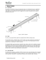
Страница 13: ...m the live zone in the section to the rollers above the tail pulley Optional power takeoff PTO timing pulleys may also be installed on a tail section to drive an additional conveyor section from the belt of the RLVAC conveyor 3 5 Intermediate Beds Intermediate beds contain one or more live roller zones and modules An intermediate bed consists of conveying rollers on the top with pressure rollers m...

Страница 14: ...d end of the skew section contain short sections of straight banded conveyor which is banded to the bed section before or after the skewed section to allow for the routing pulleys that redirect the belt This arrangement prevents tracking and belt wear issues that would be caused if the belt ran directly on the skewed conveying rollers Other than the difference in roller spacing caused by the extra...

Страница 15: ...ny bed section lengths They can range from two inches to hundreds of feet The mark number is used to help identify where the piece of equipment will go within the system layout Every bed section of conveyor will have 2 stickers One sticker on the infeed end of the bed and one sticker on the discharge end of the bed Each sticker will contain the following information BSC Project Number and Name Mod...

Страница 16: ...on the skid Figure 6 shows a sample of a skid label These stickers are placed on the surface of each skid RLVAC conveyor may arrive in multiple skids for the same mark number The number of skids shipped is dependent on the OAW and OAL of the mark number Upon receiving the skid on site please inspect for any visual damage of the equipment If there are any damages please contact your BSC representat...

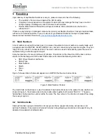
Страница 17: ...port and adjust if necessary Final heights will be set after the supports and conveyor are installed 5 2 Setting the Conveyor 1 Check the flow direction on the mark stickers to ensure that conveyor is installed in the correct order and that each section is facing the correct direction 2 Starting from one end place the conveyor onto the support structure and fasten with 3 8 16 carriage bolts and se...

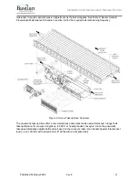
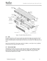
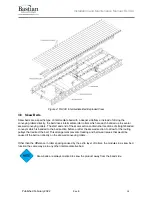
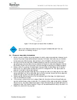
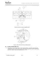
Страница 18: ...ails 3 Remove either the upstream or downstream conveying roller 1 immediately next to the bed break Drop in an upper pressure plate 76 and a 3 L carriage bolt 77 The upper pressure plate sits in notches in the two bed spacers 4 Push a spring pressure plate assembly 80 up through the holes in the bed spacers The rubber springs will press over the two protruding pins on the two modules Ensure that ...

Страница 19: ...gure 9 Skew Transition Pressure Assembly Detail 5 4 Leveling and Straightening 1 Starting at one end use a laser level or other accurate method to check the sideframe height at each bed break on both sides of the conveyor and adjust the supports as needed All bed breaks should be in the same plane and level side to side 1 16 ...

Страница 20: ...important for correct functionality For belts with traction material on both sides keeping the shiny layer towards the conveying rollers will reduce noise 3 Tape a thin piece of metal or stiff cardboard to the end of the belt to keep the end straight and help guide it through the conveyor Make sure the final thickness is less than 1 4 If the belt is prepared for a hot splice joint it will have a s...

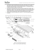
Страница 21: ...side of the belt Note that the belt moves opposite of product flow so the upstream side of the belt is towards the discharge end of the conveyor if the belt splice is on top See Figure 11 Belt Lacing Figure 11 Belt Lacing 5 5 1 Belt Routing Screw Takeup Drive 1 Remove the takeup guards on both sides of the drive Remove the access panels on the drive side opposite the gearmotor See Figure 12 Screw ...

Страница 22: ...nd the drive snub roller are set square to the drive frame and approximately centered within their slots Adjust if necessary before the belt is installed Using the routing shown in Figure 13 Screw Takeup Drive Belt Routing thread the belt through the drive The drive pulley will not turn easily with most gearmotor selections so the belt will need to be pushed rather than pulled past the pulley by p...

Страница 23: ...rawings for exploded views and details a If the takeup pulley does not slide freely temporarily unhook the air hose between the air regulator and the tensioning cylinder to break the vacuum in the tensioning cylinder Ensure that no dirt or foreign material gets into the air system and reinstall the air hose as soon as the takeup pulley has been moved 3 Check both chains on the takeup pulley to ens...

Страница 24: ...ng pulleys 2 Remove an extra no groove roller at each end of the skew section on the adjacent beds These will be replaced with the extra grooved rollers and bands which ship with every skew section 3 Route the belt underneath the crowned routing pulley 81 and over the two straight routing pulleys 37 See Figure 16 Skewed Bed Belt Routing for details 4 Route the belt between the pressure module roll...

Страница 25: ...maintenance and repair purposes Sites with only a few hot spliced belts may choose to hire a local belt service company instead of investing in the tooling and required expertise Belt hot splicing requires significant expertise and skill to achieve a fully fused straight result It is strongly recommended to make several practice splices with scrap belting before attempting to make a finished splic...

Страница 26: ...lt to assemble accurately b The splice may not close to the full theoretical distance This is acceptable as long as there are no visible gaps between the fingers Use the alignment markings to ensure the fingers are inserted the same distance across the width of the belt as in the lower image of Figure 17 Belt Splice Alignment where the alignment marks line up even though the fingers are not fully ...

Страница 27: ...ot Pressing Parameters 15 Adjust the hot press controller to the specified upper and lower platen temperatures and soak time in Table 3 Belt Hot Pressing Parameters and start the hot press cycle See the user manual for your hot press for information on how to adjust its parameters Table 3 Belt Hot Pressing Parameters Figure 17 Belt Splice Alignment ...

Страница 28: ...C 122 F or lower before opening the press Opening the press before the splice has cooled fully can cause the splice to distort or compromise its strength and also poses a burn hazard 17 Unclamp and remove the press and the guide block from around the belt Figure 18 Completed Belt Splice 18 Inspect the splice on both sides of the belt for complete fusion The outlines of the fingers should be fully ...

Страница 29: ... not under tension before cutting a Belts with a total length longer than approximately 300 feet may have a second factory splice In general the field splice should be removed when re splicing because it will be of less consistent quality than the factory splice If both splices are of high quality then either may be removed 3 Insert one end of the belt into the die cutter 4 Position the cut area s...

Страница 30: ...ller Positions for Intermediate Beds measured as distances in inches from the infeed end of the section on each intermediate bed section a Sections containing drive modules ship with return rollers pre installed and tails do not receive any return rollers 2 When installing each return roller module verify that the roller is set square at one limit of its travel on both sides The return roller is i...

Страница 31: ... tracking zones and remove all conveying rollers from the zone Remove the finger guards if the zone has them 4 Remove the adjustable center pressure roller and brackets 30 from the pressure module 5 On 2 roller center conveyor move the fixed pressure rollers nearest the adjustable center roller location to match the roller locations shown in Figure 20 Pressure Roller Locations for 2 RC Pressure Mo...

Страница 32: ...cessary to band the entire zone together as long as at least one banded roller engages with the belt on either side of the heavy duty roller 6 rollers for 3 RC or 8 rollers for 2 RC The bands may be installed on either side of the conveyor if needed 10 The non grooved rollers and pressure roller that were removed during the install process may be added to the system spares Figure 20 Pressure Rolle...

Страница 33: ...Installation and Maintenance Manual RLVAC Published February 2022 Rev B 33 Figure 21 Pressure Roller Locations for 3 RC Pressure Modules ...

Страница 34: ... most cases this will be every 60 but the pressure module spacing may vary depending on bed length Tension both the pressure assemblies at each bed break that were installed in section 5 3 and the pre installed pressure assemblies within each bed section 3 Fully tighten each pressure assembly nylock 79 until the lower pressure plate 80 contacts the bottom of the bed spacer on both sides This setti...

Страница 35: ...ushing bolts according to the procedure in the PPI bushing installation guide 8 Reference the BSC RLCAC or RLSAC Installation and Maintenance Manuals for details on PTO tensioner installation and belt tensioning Installation procedure will vary slightly depending on the model type of the driven conveyor 9 Install the PTO guard 5 10 Electrical Installation 5 10 1 AC Motor Installation 1 The conveyo...

Страница 36: ...stalled then the belt may be tensioned 2 See Figure 24 Screw Takeup Drive Belt Routing which is a duplicate of the same figure from section 5 5 1 for easier reference 3 Ensure the takeup jam nuts are loosened where both takeup screws turn freely 4 Back off both sleeve jam nuts several inches away from the plastic spring sleeves 5 Alternately turn the takeup screws clockwise to tighten the belt It ...

Страница 37: ...tensioning an existing belt tighten until the tension indicator is within the raised portion of the indicator window indicated by target tension in Figure 25 Tension Indicators The tension indicators will only display correct tension when the belt is at rest and unloaded When the belt is moving with a load on the conveyor belt tension will read lower than its actual static value 12 Measure between...

Страница 38: ...s tracking off where it exits the drive then adjust the non crowned lower routing roller The crowned upper routing roller should be set square to the drive frame 5 12 2 Pneumatic Takeup Drives 1 Once the belt is installed and joined all return rollers and tracking rollers have been installed and any guards have been reinstalled on the drive section then the belt may be tensioned 2 The pneumatic ta...

Страница 39: ...ned evenly no further adjustment is necessary Table 5 Pneumatic Takeup Pressure Settings PRESSURE LACED BELT HOT SPLICED BELT Minimum Pressure psi 18 5 52 Target Pressure psi 20 54 Maximum Pressure psi 20 5 57 5 Once the conveyor is running check belt tracking through the drive If adjustments are necessary it is recommended to adjust the tracking bracket on the non motor side only for easier acces...

Страница 40: ...feed tail at the next tracking module or at the discharge tail if the conveyor is short The snub roller at the infeed tail is best used to direct the belt after it exits the infeed tail on the return span e Do not use the adjustable center module rollers except for those in the tracking modules Keep them set square until the belt is fully tracked Live roller conveyor should generally not require a...

Страница 41: ...ers should be used sparingly only as necessary If it becomes necessary to adjust a large number of module tracking rollers or to adjust nearby module rollers in opposite directions so that they fight each other s influence that would indicate a problem with section squareness or bed alignment that should be fixed first 8 Verify that the belt is tracking centered along the entire length of the conv...

Страница 42: ...r damage foreign objects and verify all personnel is clear of the equipment prior to engaging drive Ensure that all areas are clear of objects prior to loading and unloading No personnel should ever ride climb step sit on or otherwise put body weight on the conveyor Doing so puts both personnel and equipment at risk Maintenance should be performed at regular intervals to assure the safety of opera...

Страница 43: ...mity switches and photoeyes if present Secure all mounting brackets clean the lenses and reflectors and replace any that are defective or damaged After first 24 hours and every 2 months or 500 hours thereafter Check torque of all set screws see ABB Instruction Manual for DODGE Bearings for appropriate torque values 3 months or 1 000 hours Regrease all bearings with No 2 lithium complex base grease...

Страница 44: ...torque wrench and paint marked Table 7 Fastener Standard Torque Values FASTENER TYPE FASTENER SIZE TORQUE Setscrew 10 32 30 in lbs 1 4 28 72 in lbs 5 16 24 140 in lbs 3 8 24 250 in lbs Socket head cap screw 4 40 14 in lbs 8 32 48 in lbs 10 32 80 in lbs 1 4 20 167 in lbs Button head cap screw 10 32 55 in lbs 1 4 28 105 in lbs Grade 5 carriage bolt or hex head cap screw 1 4 20 101 in lbs 5 16 18 209...

Страница 45: ... Takeup Drive Sheet 1 of 1 in Appendix 2 General Arrangement Drawings for exploded views and part numbers Turn off and lock out the drive before removing guards or replacing any parts on the drive module 6 5 1 Drive Motor Replacement 1 Before removing the existing motor check motor and gearbox nameplates to verify that the replacement motor is the correct shaft size gear ratio and voltage 2 Verify...

Страница 46: ...alues in section 6 3 for tightening torque of the shoulder bolt 12 Reinstall the shaft fixing hardware ensuring that the threads are coated with anti seize 13 Reconnect the electrical connections maintaining the phase rotation that was noted when disconnecting the old motor Review the winding diagram provided on the motor nameplate or inside the junction box to ensure the motor windings are set up...

Страница 47: ...ve the tension indicator weldments 71 Leave the takeup springs 68 and guide tubes 69 on the end of the tensioner screws Slide the tensioner screws out of the way 5 Remove the bearings 66 and shaft fixing hardware on both sides of the takeup pulley 67 Do not hammer or pry on the outer races of the bearings Damage to the bearings may result 6 Slide the takeup pulley towards the drive motor until it ...

Страница 48: ...e side of the drive section See Figure 24 Screw Takeup Drive Belt Routing in section 5 12 1 for confirmation 7 Replace the bolt and lock washer on both sides of the roller If the adjustment brackets were not moved during the procedure the previous tracking setting may be maintained otherwise set the roller square to the conveyor frame 8 See section 5 12 1 for belt tensioning and tracking instructi...

Страница 49: ...e motor does not slide freely it may be binding because the motor s weight is not evenly supported Never hammer on the motor gearbox or shaft Damage to the drive pulley bearings or gearbox bearings can result 8 Inspect the shaft and shaft key File off any burrs clean the shaft of any debris or corrosion and apply a good quality anti seize compound to all exposed steel surfaces 9 Orient the new mot...

Страница 50: ...semble and torque the XT bushings on the replacement pulley following the PCI XT bushing installation instruction sheet taking care that the pulley drum is centered between the two sideframes 12 Reinstall both drive pulley bearings 49 Torque the set screws per ABB Motors MN3016 only after both bearings are fully installed and their mounting bolts are torqued 13 Follow steps 8 through 14 of section...

Страница 51: ...ain under moderate tension to determine chain wear A new chain will measure 12 1 2 and a fully worn chain will measure 12 11 16 See Figure 26 Chain Pitch Measurement b Both chains should be replaced at the same time and the sprockets should generally be replaced or rotated when the chains are replaced Figure 26 Chain Pitch Measurement Rapid chain wear is a sign of insufficient lubrication In very ...

Страница 52: ...roller 46 or 47 from both sides of the drive and raise it until it can be slid out from the belt 4 Insert the replacement roller 46 or 47 Note that the roller 46 is a crowned roller which can be identified by the shiny machined surface The crown is very slight and will generally not be visible without a straightedge to compare against Item 47 is a non crowned roller with a mill finish tube 5 Verif...

Страница 53: ...ensioning cylinder until there is no slack left in the chain 52 to avoid shock loading the takeup mechanism on first startup Verify that both sides are taking tension evenly 14 Replace any guards that were removed 15 See section 5 12 2 for belt tensioning and tracking instructions 16 Once air pressure is applied do an auditory check for any air leakage Correct any leaks that are found 6 6 8 Air Re...

Страница 54: ... set screws yet 8 Verify the tail weldment is square to the frame by referencing the tail alignment guide seen in Detail A of Figure 29 General Arrangement RLVAC Tail Sheet 1 of 1 in Appendix 2 General Arrangement Drawings The center square hole should align between the tail weldment and the sideframe on both sides 9 Slide the new pulley into place inside the loop of belt Verify belt routing with ...

Страница 55: ...pressure on the end of the hex shaft opposite the bands using a small diameter punch or similar tool until the shaft clears the frame Be careful NOT to apply a side load to the hex shaft 2 Provide upward force on the roller body until the hex is sitting above the sideframe A putty knife or other flat surface tool is recommended to be placed between the hex shaft and the inside of the frame This wi...

Страница 56: ...ow the same procedure as in section 6 8 1 to remove and replace a pressure roller It is not necessary to use a putty knife on the galvanized pressure pans 3 Double check the correct positioning of the new pressure roller against Figure 20 Pressure Roller Locations for 2 RC Pressure Modules or Figure 21 Pressure Roller Locations for 3 RC Pressure Modules in section 5 7 4 Reinstall any removed conve...

Страница 57: ...2 1 for screw takeup drives or section 5 12 2 for pneumatic takeup drives 2 Remove the straight banded rollers 22 at the beginning or end of the skew section until the routing roller 37 or 81 is accessible See Figure 27 General Arrangement RLVAC Bed Section Sheet 1 of 2 and Figure 28 General Arrangement RLVAC Bed Section Sheet 2 of 2 for details 3 One side of the roller hex will depress Push the r...

Страница 58: ...ul not to overstretch or damage it 9 Using the same screwdriver technique place the new band in the center of the roller Adjust its position until it is running true 10 Repeat with the remaining two new bands Adjust all three bands until they are touching without overlaps 11 Follow the procedures in section 5 6 for installation of the tracking roller If tracking band installation is difficult use ...

Страница 59: ...5 This movement in the motor is acceptable There is no physical damage to the conveyor section Wobble at the back of the motor is 0 25 The drive pulley shaft is bent out of tolerance Replace the drive pulley shaft Loud hum from the motor Motor doesn t run or runs slowly Missing phase connection incorrect winding configuration or other incorrect motor wiring Verify motor wiring Motor is stalled Che...

Страница 60: ...ers from the edge of the belt Check and repair any damage to the belt splice If the belt is less than 3 wide Schedule belt replacement Fix the tracking problems before belt replacement so as to avoid damage to the new belt Melted or severely worn spots on the belt facing The belt is slipping on the drive pulley Re tension the belt Replace if needed Clean the belt and drive pulley if severe contami...

Страница 61: ... is cut crooked this is very rare Remove belt from the conveyor spin it 180 and re install it without making any other changes If the belt tracks off to the other direction the belt is defective Contact BSC for replacement information If the belt tracks off to the same direction as before the belt is not at fault Zone has poor drive or product hangs up Insufficient module spring pressure Fully tig...

Страница 62: ...PM GEAR RATIO MOTOR SIDE PART NUMBER 1 250 BF38 1 4 68 67 18 Left A013DM 10135 Right A013DM 10136 93 49 38 Left A013DM 10129 Right A013DM 10130 125 36 69 Left A013DM 10123 Right A013DM 10124 170 26 90 Left A013DM 10119 Right A013DM 10120 1 2 68 67 18 Left A013DM 10201 Right A013DM 10202 93 49 38 Left A013DM 10195 Right A013DM 10196 125 36 69 Left A013DM 10189 Right A013DM 10190 160 28 72 Left A013...

Страница 63: ...ight A013DM 10366 151 30 38 Left A013DM 10361 Right A013DM 10362 216 21 22 Left A013DM 10353 Right A013DM 10354 271 16 89 Left A013DM 10349 Right A013DM 10350 384 11 94 Left A013DM 10345 Right A013DM 10346 2 151 30 38 Left A013DM 10421 Right A013DM 10422 216 21 22 Left A013DM 10413 Right A013DM 10414 271 16 89 Left A013DM 10409 Right A013DM 10410 384 11 94 Left A013DM 10405 Right A013DM 10406 3 21...

Страница 64: ...NO GRV 3 8 16 FEMALE THREAD 17mm SHAFT 7 00in BF ABEC 1 HEAVY DUTY A001RL 10306 24 TRACKING BAND 0 5in W 5 88in L 0 03in THICK 92A BLACK A001BA 10059 25 BRACKET ROLLER AC MODULE TRACKING ADJUSTMENT FEMALE THREAD Z022RC 10292 26 HHCS 3 8 16 UNC GR5 ZINC PLATED 5 8 L FULL THD A003HC 00086 27 SERRATED BELLEVILLE LOCK WASHER NARROW FOR SHCS 3 8 AND M10 SCREW SIZE A003IW 00007 28 CARRIAGE BOLT 1 4 20 U...

Страница 65: ...ONNECTING LINK ANSI 50 ROLLER CHAIN SLIP FIT A013CH 10001 54 SLIDER BLOCK ROLLER AC HEAVY DUTY DRIVE UHMW Z022RC 10001 55 AIR CYLINDER 3 25in BORE 50in STROKE 1in ROD 3 4 10 UNC ROD END THREAD DOUBLE ACTING FRONT FLANGE MOUNT CUSHIONS BOTH ENDS NFPA TIE ROD INTERCHANGEABLE A015PA 10007 56 MUFFLER 1 2 NPTM SINTERED BRASS LOW PROFILE A016FT 10030 57 ELBOW 1 2 NPT MALE TO 3 8 PUSH A016FT 10034 58 FIL...

Страница 66: ...021RP 10006 76 PRESSURE PLATE ROLLER AC MODULE SPRING UPPER Z022RC 10136 77 CARRIAGE BOLT 3 8 16 UNC GR5 ZINC PLATED 3 L PARTIAL THD A003CB 00076 78 SAE FLAT WASHER 3 8 SCREW SIZE 0 81 OD ZINC PLATED A003SW 00011 79 NUT NYLOCK 3 8 16 UNC GR5 A003LN 00011 80 ASM ROLLER AC LR SPRING PRESSURE PLATE Z020RA 10092 81 ROLLER 3 5in OD NO GRV 11 16 HEX 7in BF HEAVY DUTY RADIAL CROWNED A001RL 10234 82 SKATE...

Страница 67: ...Installation and Maintenance Manual RLVAC Published February 2022 Rev B 67 Figure 27 General Arrangement RLVAC Bed Section Sheet 1 of 2 ...

Страница 68: ...Installation and Maintenance Manual RLVAC Published February 2022 Rev B 68 Figure 28 General Arrangement RLVAC Bed Section Sheet 2 of 2 ...

Страница 69: ...Installation and Maintenance Manual RLVAC Published February 2022 Rev B 69 Figure 29 General Arrangement RLVAC Tail Sheet 1 of 1 ...

Страница 70: ...Installation and Maintenance Manual RLVAC Published February 2022 Rev B 70 Figure 30 General Arrangement Belt Under Roller AC Pneumatic Takeup Drive Sheet 1 of 1 ...

Страница 71: ...Installation and Maintenance Manual RLVAC Published February 2022 Rev B 71 Figure 31 General Arrangement Belt Under Roller AC Screw Takeup Drive Sheet 1 of 1 ...

Страница 72: ...ed used or disclosed without written permission from Bastian Solutions It may not be used in whole or in part for any purpose other than its intended purpose as an operation installation and maintenance manual for the product or products described herein Bastian Solutions reserves the right to revise the contents of this document as necessary Bastian Solutions LLC 1821 Bastian Court Westfield IN 4...

Отзывы: