Installation and Maintenance Manual: RLVAC
Published February 2022
45
Turn off and lock out the drive before removing guards or changing belt tension.
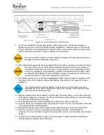
2. With the conveyor locked out, remove all belt tension. Pneumatic takeups will lose tension when
the air supply is locked out.
3. For conveyors with PTO, disconnect the driven conveyors by removing the PTO belt(s).
4. Remove conveying rollers and finger guards as needed to access a section of the old belt.
5. Remove the lacing pin for a laced belt, or cut the old belt if it is hot spliced.
6. Connect the end of the new belt to the end of the old belt. Make sure the final thickness is less
than 1/4”. Laced belts may be connected together using the lacing and pin. Hot spliced belts will
need to be taped together.
7. Using the old belt, pull the new belt through the conveyor. Generally, the drive pulley will not turn
freely, so this process may need to be done in stages to get the belt past the drive.
8. See section 5.5 for instructions on joining the new belt, and belt routing information if needed.
9. Reinstall any PTO belt(s), conveying rollers, and guards that were removed.
6.5 Screw Takeup Drive
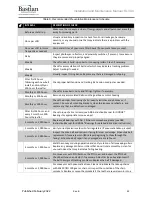
See Figure 31: General Arrangement, Belt Under Roller AC, Screw Takeup Drive, Sheet 1 of 1 in
Appendix 2: General Arrangement Drawings for exploded views and part numbers.
Turn off and lock out the drive before removing guards or replacing any parts on the
drive module.
6.5.1 Drive Motor Replacement
1. Before removing the existing motor, check motor and gearbox nameplates to verify that the
replacement motor is the correct shaft size, gear ratio, and voltage.
2. Verify that electrical power is not present and is properly locked out, then disconnect the electrical
connections in the motor conduit box. Note the phase rotation for later so the replacement motor
will spin the same direction.
Only qualified electricians should connect or disconnect motor terminals. Incorrect
connection can cause hazardous voltages to be present on the outer case of the motor
or connected equipment, and can damage the motor or VFD.
For motors with VFDs, hazardous electrical power may be present for several minutes
after the supply is turned off and locked out, due to the VFD’s internal capacitors.
3. Remove the plastic dust cover, shaft fixing bolt, and shaft retaining washer in the end of the
motor’s hollow bore.
4. Support the motor from underneath.
Larger gearmotors are very heavy and will require mechanical assistance (e.g. a pump
cart) to remove and replace safely. Always use safe lifting practices and be cautious of
pinch points that can be created between the motor and its supports.

