Installation and Maintenance Manual: RLVAC
Published February 2022
24
5. Check that both routing rollers and the drive snub roller are set square to the drive frame and
approximately centered within their slots. Adjust if necessary before the belt is installed.
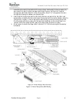
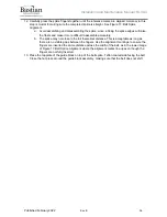
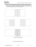
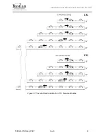
6. Using the routing shown in Figure 15: Pneumatic Takeup Drive Belt Routing, thread the belt
through the drive. The drive pulley will not turn easily with most gearmotor selections, so the belt
will need to be “pushed” rather than “pulled” past the pulley by providing slack just before the
pulley.
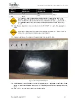
7. Reinstall all the guards that were removed.
8. Do not tension the belt at this stage. Refer to section 5.12.2 for belt tensioning instructions.
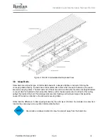
Figure 15: Pneumatic Takeup Drive Belt Routing
5.5.3 Belt Routing: Skewed Beds
1. Remove the banded rollers (22) at the start and end of the skew section to gain access to the
routing pulleys.
2. Remove an extra no-groove roller at each end of the skew section, on the adjacent beds. These
will be replaced with the extra grooved rollers and bands which ship with every skew section.
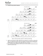
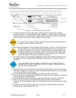
3. Route the belt underneath the crowned routing pulley (81) and over the two straight routing
pulleys (37). See Figure 16: Skewed Bed Belt Routing for details.
4. Route the belt between the pressure module rollers (2) and the lower, non-skewed driving rollers
(22). If the skew section is very long, it may be helpful to remove a few conveying rollers in the
center of the section for access.
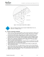
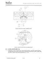
Figure 16: Skewed Bed Belt Routing
5. At the other end of the skew section, route the belt underneath the crowned routing pulley (81)
and over the two straight routing pulleys (37), then continue routing the belt through the
remainder of the conveyor.
6. On the belt return span, the belt passes underneath the two fixed narrow rollers (2) which adjust
the height of the belt return path. Belt return assemblies on either side of the skew section
constrain the belt return (installed after the belt is fully routed).

