background image

Operation and Features

Basler L301kc

3-35

DRAFT

3.10 Configuration Sets

The camera’s adjustable parameters are stored in
configuration sets and each configuration set contains
all of the parameters needed to control the camera.
There are three different types of configuration sets: the
Work Set, the Factory Set, and User Sets.

Work Set

The Work Set contains the current camera settings and
thus determines the camera’s present performance,
that is, what your image currently looks like. The Work
Set is stored in the camera RAM. The configuration
parameters in the Work Set can be altered directly using
the Camera Configuration Tool or using binary
programming commands. 

Factory Set

When a camera is manufactured, a test set up is performed on the camera and an optimized
configuration is determined. The Factory Set contains the camera’s factory optimized
configuration. The Factory Set is stored in non-volatile memory on the EEPROM and can not be
altered.

User Sets

User Sets are also stored in the non-volatile EEPROM of the camera. The camera has 15 User
Sets. Each User Set initially contains factory settings but User Sets can be modified. Modification
is accomplished by making changes to the Work Set and then copying the Work set into one of
the User Sets. The Camera Configuration Tool or binary commands can be used to copy the Work
Set into one of the User Sets.

Startup Pointer

When power to the camera is switched off, the Work set in the RAM is lost. At the next power on,
a configuration set is automatically copied into the Work Set. The Startup Pointer is used to specify
which of the configuration sets stored in the EEPROM will be copied into the Work Set at power
on. The Startup Pointer is initially set so that the Factory Set is loaded into the Work Set at power
on. This can be changed using the Camera Configuration Tool or binary commands. The Startup
Pointer can be set to the Factory Set or to any one of the User Sets. So, for example, if the Startup
Pointer is set to User Set 13, then User Set 13 will be copied into the Work Set at power on.


You can work with configuration sets and the startup pointer using either the Camera
Configuration Tool Plus (see Sectio

4.1

) or binary commands (see Section 

4.2

). 

With the Camera Configuration Tool Plus, you can use the Camera selection in the File Menu to
copy the Work Set to a User Set, to Copy a User Set or the Factory Set to the Work Set, or to set
the Startup Pointer. 

With binary commands you use the Copy Work Set to User Set command, the Copy Factory Set
or User Set to Work Set command, and the Select Startup Pointer command to manipulate
configuration sets (see Sections 

4.2.8.1

 through 

4.2.8.3

).

Figure 3-27: Config Sets

Содержание L301kc

Страница 1: ...Basler L301kc USER S MANUAL Document Number DA00051806 Release Date 13 July 2007...

Страница 2: ...equipment The shielded interface cable recommended in this manual must be used with this equipment in order to comply with the limits for a computing device pursuant to Subpart J of Part 15 of FCC Ru...

Страница 3: ...3 599 vc support europe baslerweb com Americas Basler Inc 855 Springdale Drive Suite 160 Exton PA 19341 U S A Tel 1 877 934 8472 Fax 1 877 934 7608 vc support usa baslerweb com Asia Basler Asia Pte Lt...

Страница 4: ......

Страница 5: ...ignals 2 8 2 5 1 Pixel Clock 2 8 2 5 2 Line Valid Bit 2 8 2 5 3 Data Valid Bit 2 8 2 5 4 Video Data 2 8 2 5 5 Video Data Output Modes 2 10 2 5 6 Integrate Enabled Signal 2 18 2 6 RS 644 Serial Communi...

Страница 6: ...Moving Vertical Gray Gradient 3 33 3 9 3 Test Image Three Moving Horizontal Gray Gradient 3 33 3 9 4 Test Image Four Red Gradient 3 34 3 9 5 Test Image Five Green Gradient 3 34 3 9 6 Test Image Six B...

Страница 7: ...ommand 4 22 4 2 7 Query Commands 4 23 4 2 7 1 Read Microcontroller Firmware Version 4 23 4 2 7 2 Read FPGA Firmware Version 4 23 4 2 7 3 Read Vendor Information 4 23 4 2 7 4 Read Model Information 4 2...

Страница 8: ...sler L301kc DRAFT 6 2 1 No Image 6 2 6 2 2 Poor Quality Image 6 4 6 2 3 Interfacing 6 5 6 2 4 RS 644 Serial Communication 6 6 6 3 Before Calling Basler Technical Support 6 7 Revision History i Feedbac...

Страница 9: ...ured housing Important features are Tri linear Color Array High responsivity Electronic exposure time control High signal to noise ratio Spatial Correction Area of Interest AOI scanning Digital Shift...

Страница 10: ...ial correction not enabled Minimum Line Rate 1 kHz Video Output Type Camera Link LVDS RS 644 LVDS when used with the optional Basler Interface Converter for k cameras k BIC Video Output Formats Single...

Страница 11: ...tral Responsivity L Color filter arrays become transparent after 700 nm To maintain spectral balance use of a suitable IR cut off filter is recommended The filter should transmit in a range of 400 nm...

Страница 12: ...0 C 80 C 4 F 176 F Storage Humidity 5 95 relative non condensing 1 2 2 Ventilation Allow sufficient air circulation around the camera to prevent internal heat build up in your system and to keep the c...

Страница 13: ...e of the CCD sensor if possible If you must clean it use a soft lint free cloth dampened with a small quantity of high quality window cleaner Do not use methylated alcohol Because electrostatic discha...

Страница 14: ...Introduction 1 6 Baslert L301kc DRAFT...

Страница 15: ...f the camera a 26 pin 050 Mini D Ribbon MDR female connector used to transmit video data control data and configuration data a 6 pin micro miniature push pull receptacle used to provide power to the c...

Страница 16: ...DS Data from Camera Link Transmitter 6 Tx X3 18 Tx Clk Output Camera Link LVDS Transmit Clock from Camera Link Transmitter 5 Tx Clk 12 CC4 Not Connected 25 CC4 24 CC3 Output RS 644 LVDS Integrate Enab...

Страница 17: ...is the Hirose micro miniature locking plug Part HR10A 7P 6S A plug of this type will be shipped with each camera The plug should be used to terminate the cable on the power supply for the camera Pin...

Страница 18: ...hat you use the National Semiconductor DS90CR288 the National Semiconductor DS90CR288A or an equivalent Detailed data sheets for these components are available at the National Semiconductor web site w...

Страница 19: ...ignal defined in the specification Detailed spec sheets for these devices are available at the National Semiconductor web site www national com The schematic in Figure 2 3 shows the interface for L301...

Страница 20: ...Camera Interface 2 6 Basler L301kc DRAFT Figure 2 3 Camera Frame Grabber Interface...

Страница 21: ...frequency of the ExSync signal determines the camera s line rate Note that ExSync is edge sensitive and therefore must toggle Minimum high time for the ExSync signal is 0 35 s The ExSync signal is typ...

Страница 22: ...The data valid bit is not used on this camera and should be ignored The status of this bit is always identical to the line valid bit 2 5 4 Video Data Table 2 3 lists the assignment of pixel data bits...

Страница 23: ...7 RxOUT7 Green Pixel Bit 0 Pixel Bit 8 Not Used Pixel A Bit 8 Pixel B Bit 0 B1 TxIN8 RxOUT8 Green Pixel Bit 1 Pixel Bit 9 MSB Not Used Pixel A Bit 9 MSB Pixel B Bit 1 B2 TxIN9 RxOUT9 Green Pixel Bit 2...

Страница 24: ...pixel number one in the red line eight of the bits will contain the data for pixel number one in the green line and eight of the bits will contain the data for pixel number one in the blue line On th...

Страница 25: ...e mode Figure 2 4 20 MHz 8 Bit RGB Mode with Edge or Level Controlled Exposure 1 pixel clock cycle PClk 0 05 s The pixel data that is transmitted out of the camera is affected by the spatial correctio...

Страница 26: ...he pixel data that is transmitted out of the camera is affected by the spatial correction settings see Section 3 5 5 This diagram assumes that the area of interest feature is not being used With the a...

Страница 27: ...ock the line valid bit will be high Ten of the bits transmitted during this clock cycle will contain the data for pixel number two in the red line On the fifth cycle of the pixel clock the line valid...

Страница 28: ...This diagram assumes that the area of interest feature is not being used With the area of interest feature enabled the number of pixels transferred could be smaller see Section 3 8 TIMING CHARTS ARE...

Страница 29: ...in the blue line and the ten Pixel B bits will contain dummy data which should be ignored On the third cycle of the pixel clock the line valid bit will be high The ten Pixel A bits trans mitted on th...

Страница 30: ...e or Dual Pixel 8 Bit Mode with Edge or Level Controlled Exposure 1 pixel clock cycle PClk 0 025 s The pixel data that is transmitted out of the camera is affected by the spatial correction settings s...

Страница 31: ...ta that is transmitted out of the camera is affected by the spatial correction settings see Section 3 5 5 Pixel data is always transmitted in red green blue order This diagram assumes that the area of...

Страница 32: ...d signal from the camera are not attached to the pins in the frame grabber end of the cable Instead the wires are unterminated and are folded back inside of the connector housing on the frame grabber...

Страница 33: ...frame grabber or the Basler CPA driver See Section 4 2 for details on the binary command format 2 6 1 Making the Serial Connection Frame grabbers compliant with the Camera Link specification are equip...

Страница 34: ...or complete information on the k BIC refer to the k BIC User s Manual and the k BIC installation guide 2 8 DC Power The L301kc requires 12 VDC 10 power An appropriate power supply is available from Ba...

Страница 35: ...e begins on the rising edge of ExSync and accumulated charges are read out when the programmed exposure time ends A free run mode that allows the camera to operate without an ExSync signal is also ava...

Страница 36: ...Operation and Features 3 2 Basler L301kc DRAFT Figure 3 1 Pixels and Shift Registers Figure 3 2 L301kc Block Diagram...

Страница 37: ...trolled mode and programmable mode In ExSync edge controlled mode the pixels are exposed and charge is accumulated over the full period of the ExSync signal rising edge to rising edge The falling edge...

Страница 38: ...grammable exposure time control mode If you select the programmable mode you must also enter an exposure time When you enter an exposure time the configuration tool will automatically set the Timer 1...

Страница 39: ...ation are available edge controlled and programmable In free run edge controlled mode the pixels are exposed and charge is accumulated over the full period of the internal control signal rising edge t...

Страница 40: ...rate Depending on whether spatial correction is used the maximum line rate is either 8 0 kHz with spatial correction or 9 2 kHz without spatial correction The minimum line rate must not be lower than...

Страница 41: ...ion 4 1 or binary commands see Section 4 2 With the Camera Configuration Tool Plus you use the Video Data Output Mode setting in the Output parameter group With binary commands you use the Video Data...

Страница 42: ...nter to center Figure 3 8 L301kc Sensor Face Due to the spacing between lines each line will have a different line of view on any object that is passing the camera as shown in Figure 3 9 Whenever a li...

Страница 43: ...at three different times This means that the red information for area A the green information for area A and the blue information for area A will be collected during three different line captures So i...

Страница 44: ...we must take the blue line data and combine it with the green data from 8 line captures earlier and the red data from 16 line captures earlier In order to do this the data from the last 17 line captu...

Страница 45: ...tion is disabled when the camera is used in a 10 bit mode Test Images The camera must not be set for test image one or for test image two When either of these test images is active the Spatial Correct...

Страница 46: ...ion parameters set properly the image will show no color halos Position Encoder You must use a position encoder to monitor the movement of the system s conveyor You must also use the encoder output to...

Страница 47: ...e constant in size The color of the halo visible on one side of the elements in the captured image will be different from the color of the halo on the other side For example lettering in the captured...

Страница 48: ...er side For example lettering in the captured image may show orange colored halos on both sides of each letter The haloing is less obvious on elements in the captured image that are closer to the cent...

Страница 49: ...short object from a different perspective than they view a tall object To make sure that all objects are in perspective even if they strongly differ in height use of a telecentric lens setup is recomm...

Страница 50: ...ur captured images is determined by the value of n in the magnification equation The value can be set from 1 to 16 If the value is set to 8 the aspect ratio of the captured images will be 1 to 1 The a...

Страница 51: ...tep 2 Calculate the magnification 0 07 1 14 29 is the standard symbol for magnification and is usually expressed as a ratio Step 3 Calculate the line of view of the sensor L 419 60 mm Step 4 Use the O...

Страница 52: ...line 1 11 916 is the standard symbol for magnification and is usually expressed as a ratio Step 2 Calculate the conveyor movement necessary to move the image 112 m Step 3 Calculate the number of encod...

Страница 53: ...ded to make 1 4 mm of conveyor movement result in 112 m movement of the image 1 12 5 Step 3 Calculate the width of conveyor that will be viewed by each sensor line at this magnification 29 372 mm x 12...

Страница 54: ...ptics Recommendation Guide and the Makro xls Spreadsheet to select an appropriate lens and to determine the mounting distance for your camera Step 5 Make sure that the Spatial Correction Starting Line...

Страница 55: ...which stored exposures will be combined in order to obtain full RGB data for an area on the image see Section 3 5 1 For example when the delay is set to 8 and the starting line is set to red line the...

Страница 56: ...ADC Increasing or decreasing the offset moves the signal up or down the measurement scale but does not change the signal amplitude For most applications black should have a gray value of 1 and white s...

Страница 57: ...the lighting conditions of your application follow the procedure described below 1 Set the red line gain the green line gain and the blue line gain all to the decimal starting value of 96 2 Out of th...

Страница 58: ...operating in 8 bit output mode an increase of 16 decimal in the red line setting will result in a positive offset of 1 in the digital values output for the pixels in the red line of the sensor An incr...

Страница 59: ...ut from the CCD sensor When the camera is operating in 10 bit output mode by default the camera transmits the 10 bits that are output from each ADC Shift Once When the camera is set to shift once the...

Страница 60: ...r no shift that it is viewing a uniform white target and that under these conditions the reading for the brightest pixel is 100 If you changed the digital shift setting to shift three times the readin...

Страница 61: ...put from the camera will include bit 8 through bit 1 from each ADC The result of shifting once is that the output of the camera is effectively doubled For example assume that the camera is set for no...

Страница 62: ...ely multiplied by eight For example assume that the camera is set for no shift that it is viewing a uniform white target and that under these conditions the reading for the brightest pixel is 20 If yo...

Страница 63: ...the readings are below 512 you can safely use the 2X digital shift setting If all of the readings are below 256 you can safely use the 2X or 4X digital shift setting If all of the readings are below...

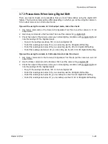
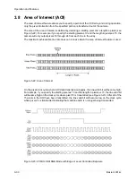
Страница 64: ...m each line in the array The maximum achieveable line rate does not increase when the area of interest feature is used Figure 3 22 Area of Interest On the pixel clock cycle where AOI data transmission...

Страница 65: ...g Pixel and Area of Interest Length in Pixel commands see Sections 4 2 4 8 and 4 2 4 9 L If you use a frame grabber which does not take the falling edge of the line valid bit into account you must als...

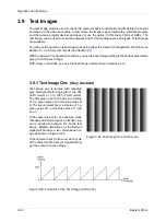
Страница 66: ...eters group to set the test image With binary commands you use the Test Image command see Section 4 2 5 3 9 1 Test Image One Gray Gradient Test image one is formed with repeated gray scale gradients r...

Страница 67: ...ue value of 0 The second pixel has a red value of 1 a green value of 1 and a blue value of 1 and so on The right half of the image is formed with repeated horizontal gray scale gradients ranging from...

Страница 68: ...t image four is formed with repeated blue gradients ranging from0 to 255 8 bit mode or 0 to 1023 10 bit mode The first pixel in each line has a red value of 0 a green value of 0 and a blue value of 0...

Страница 69: ...of the User Sets The Camera Configuration Tool or binary commands can be used to copy the Work Set into one of the User Sets Startup Pointer When power to the camera is switched off the Work set in th...

Страница 70: ...with the Camera Configuration Tool Plus see Section 4 1 You check the Status indicator in the Camera Information parameter group to see if an error code is present with binary commands You use the Ca...

Страница 71: ...lication the following parameters can also be configured Spatial Correction Gain Offset Area of Interest Digital Shift The L301kc is programmable via the Camera Link serial port on the frame grabber T...

Страница 72: ...rograms If not please refer to your Microsoft Windows manual 4 1 1 Opening the Configuration Tool 1 Make sure that the properties for the RS 644 serial port on your frame grabber are properly configur...

Страница 73: ...a parameter names always appear in the left column of the list The current setting for each parameter appears in the right column By default an additional Parameter Description window is displayed In...

Страница 74: ...you make to the Work Set using the configuration tool will be lost when the camera is switched off To save changes you make to the Work Set open the Camera menu of the config uration tool and save th...

Страница 75: ...u can use either the API from the DLL delivered with the grabber or the Basler CPA driver for executing the binary commands The Basler CPA Camera Port Access is a software framework which standardizes...

Страница 76: ...or is on the left highest bit of the command ID and the LSB of the descriptor is on the right lowest bit of the data length DATA Data field Size Number of bytes indicated in the Data Length portion of...

Страница 77: ...T ACK NAK Response Positive frame acknowledge negative frame acknowledge Size 1 byte The value for a positive frame acknowledgement is 0x06 and for a negative frame acknowledgement is 0x15 L All value...

Страница 78: ...the camera receives a read command with an unknown command ID in the descriptor it will respond with an ACK but will not send a frame If the host sends a read command and gets no ACK NAK the host can...

Страница 79: ...in the response No data bytes are actually included in the read command 0xC1 is the block check character BCC See page 4 10 for instructions on calculating a BCC 0x03 is the ETX The ETX is always 0x03...

Страница 80: ...rs are shown in their binary form so in the sample calculations shown below the hexadecimal digits in our command have been converted to binary To find the XOR sum of two binary numbers you must add t...

Страница 81: ...es Type This is a read or write command Read Command Cmd ID R W Flag Data Length Data 0xC0 1 1 Response Cmd ID R W Flag Data Length Data 0xC0 0 1 1 Byte Write Command Cmd ID R W Flag Data Length Data...

Страница 82: ...is a read or write command Read Command Cmd ID R W Flag Data Length Data 0xA0 1 1 Response Cmd ID R W Flag Data Length Data 0xA0 0 1 1 Byte Write Command Cmd ID R W Flag Data Length Data 0xA0 0 1 1 By...

Страница 83: ...0 2 3 Bytes Response None Data Format Byte 1 Low byte of the Timer 1 setting Byte 2 Mid byte of the Timer 1 setting Byte 3 High byte of the Timer 1 setting Data Range The setting can range from 0x0000...

Страница 84: ...nse None Data Format Byte 1 Low byte of the Timer 2 setting Byte 2 Mid byte of the Timer 2 setting Byte 3 High byte of the Timer 2 setting Data Range The setting can range from 0x000040 to 0xFFFFFF Th...

Страница 85: ...lag Data Length Data 0xAD 0 1 1 Byte Write Command Cmd ID R W Flag Data Length Data 0xAD 0 1 1 Byte Response None Data Format Byte 1 An ID that specifies the spatial correction delay in lines see the...

Страница 86: ...n of spatial correction Type This is a read or write command Read Command Cmd ID R W Flag Data Length Data 0xAE 1 1 Response Cmd ID R W Flag Data Length Data 0xAE 0 1 1 Byte Write Command Cmd ID R W F...

Страница 87: ...ID R W Flag Data Length Data 0xA5 0 1 1 Byte Write Command Cmd ID R W Flag Data Length Data 0xA5 0 1 1 Byte Response None Data Format Byte 1 An ID that specifies the digital shift status see the table...

Страница 88: ...setting can range from 0x0000 to 0x0830 0 to 2096 When using binary commands the actual starting pixel n 1 where n is the setting made using this binary command For example if you wish to define pixe...

Страница 89: ...n setting Byte 2 High byte of red gain setting Data Range The red line gain setting can range from 0x0060 to 0x03FF which translates to a dB range of 0 dB to 33 6 dB Purpose To set the offset on the r...

Страница 90: ...setting Byte 2 High byte of green gain setting Data Range The green line gain setting can range from 0x0060 to 0x03FF which translates to a dB range of 0 dB to 33 6 dB Purpose To set the offset on the...

Страница 91: ...setting Byte 2 High byte of blue gain setting Data Range The blue line gain setting can range from 0x0060 to 0x03FF which translates to a dB range of 0 dB to 33 6 dB Purpose To set the offset on the...

Страница 92: ...sponse None Data Format Byte 1 An ID that specifies the test image see the table below ID Test Image 0x00 No test image 0x01 Test Image 1 gray gradient 0x02 Test Image 2 moving vertical gray gradient...

Страница 93: ...Byte 3 Protocol Version Purpose To read the FPGA firmware version Type This is a read only command Read Command Cmd ID R W Flag Data Length Data 0x41 1 3 Response Cmd ID R W Flag Data Length Data 0x41...

Страница 94: ...read the camera s product ID number Type This is a read only command Read Command Cmd ID R W Flag Data Length Data 0x03 1 16 Response Cmd ID R W Flag Data Length Data 0x03 0 16 16 Bytes Data Format Ze...

Страница 95: ...Length Data 0x05 0 3 3 Bytes Data Format Byte 1 Low byte of camera version BCD coded Byte 2 High byte of camera version BCD coded Byte 3 Protocol Version Purpose To read the EEPROM firmware version T...

Страница 96: ...ent If the MSB is 0 the temperature is 0 C or higher For temperatures below 0 C a two s complement representation is used that is to obtain the actual temperature the digital output must be inverted a...

Страница 97: ...ommand will return the ID for no active set This condition indicates that no valid Factory Set or User Sets were found It will also cause the yellow LED on the back of the camera to show six pulses Ty...

Страница 98: ...only command Write Command Cmd ID R W Flag Data Length Data 0x46 0 1 1 Byte Response None Data Format Byte 1 An ID that specifies the user set see the table below Set ID Set 0x01 User Set 1 0x02 User...

Страница 99: ...ng Type This is a read or write command Read Command Cmd ID R W Flag Data Length Data 0x47 1 1 Response Cmd ID R W Flag Data Length Data 0x47 0 1 1 Byte Write Command Cmd ID R W Flag Data Length Data...

Страница 100: ...elow If a bit is set to 1 the error condition assigned to that bit is present If the bit is set to 0 the error is not present Byte 1 Bit 0 No ExSync signal in the last 5 seconds Bit 1 A reset has occu...

Страница 101: ...00 0x17 38400 0x19 57600 0x1A 76800 0x1B 115200 L When changing the bitrate for serial communication use the following procedure 1 Issue the write command with the new bitrate 2 Wait one second 3 Chan...

Страница 102: ...Configuring the Camera 4 32 Basler L301kc DRAFT...

Страница 103: ...ufactured with high precision Planar parallel and angular sides guarantee precise mounting with high repeatability The L301kc camera is equipped with four M4 mounting holes on the front and two M4 mou...

Страница 104: ...Mechanical Considerations 5 2 Basler L301kc DRAFT Figure 5 1 L301kc Mechanical Dimensions in mm...

Страница 105: ...Mechanical Considerations Basler L301kc 5 3 DRAFT 5 2 F Mount Adapter Dimensions Figure 5 2 F Mount Adapter Dimensions in mm Drawing is not to scale...

Страница 106: ...oning accuracy of the sensor chip is as shown in Figure 5 3 Since translatory and rotational positioning tolerances depend on each other the worst case of maximum rotational and horizontal vertical mi...

Страница 107: ...the back of the camera is not lit it means that power to the camera is not present or is less than 10 8 Volts LED Description On Continuous The camera is OK 3 blinks ExSync has not changed state for...

Страница 108: ...he power source Yes The camera is not detecting an ExSync signal Check the ExSync signal or set the camera for Free run mode See Section 3 2 2 Call Basler Technical Support for assistance The contact...

Страница 109: ...r 1 plus the Timer 2 is no lower than the minimum sum given in Section 3 2 2 1 Are the settings OK No Correct the settings Binary Commands Did you set up free run using the CCT or with binary commands...

Страница 110: ...look noisy Other image problems Do the following Make sure that the lens cap has been removed Check the lens aperture If the images are too dark try opening the aperture Try closing the aperture if th...

Страница 111: ...fore you call for support be sure to make note of the camera settings and the frame grabber settings you are using You should also have a captured live image and a captured test image available Techni...

Страница 112: ...y a port number and a dll library name Click on an RS 644 port in the list Does a list of camera settings appear The RS 644 port is working correctly Exit this chart Yes Yes No Yes No No Does a Can t...

Страница 113: ...llect several pieces of information before you contact technical support Copy the form that appears on the next two pages fill it out and fax the pages to your local dealer or to your nearest Basler s...

Страница 114: ...ion that you use with the camera 6 Describe the problem in as much detail as possible If you need more space use an extra sheet of paper 7 If known what s the cause of the problem 8 When did the probl...

Страница 115: ...ke a copy of the parameters start the CCT select the File menu and click Dump Current Settings to File Send the generated file to Basler Technical Support If you cannot access the camera please try to...

Страница 116: ...Troubleshooting 6 10 Basler L301kc DRAFT...

Страница 117: ...ports are assigned to each Camera Link transmitter and receiver In Section 5 3 added sensor horizontal and vertical position tolerances refer enced to the sides of the camera DA00051806 13 Jul 2007 Up...

Страница 118: ...Revision History ii Basler L301kc DRAFT...

Страница 119: ...like to get your feedback to help us improve our camera documentation Please click on the link below to go to our web site and fill in our online documentation feedback form Your input is greatly appr...

Страница 120: ...Feedback iv Basler L301kc DRAFT...

Страница 121: ...28 configuration tool see camera configuration tool configuring the camera with binary commands 4 5 with the config tool 4 2 connector types 2 3 D dark signal non uniformity 1 2 data output mode see...

Страница 122: ...12 R read command error checking 4 8 example 4 9 resetting the camera with binary commands 4 22 responsivity 1 3 RS 644 output 2 20 RS 644 serial connection 2 19 S saving parameter sets 3 35 sensor t...

Страница 123: ...Index Basler L301kc vii DRAFT W weight camera 1 2 white balance 3 22 work set copying to a user set 4 28 explained 3 35 relationship to the config tool 4 3 write command error checking 4 8 example 4 9...

Страница 124: ...Index viii Basler L301kc DRAFT...

Отзывы: