
Camera Interface
Basler L301kc
2-3
DRAFT
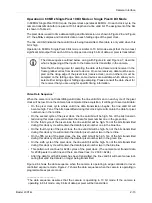
6-Pin Micro-miniature Receptacle
The pin assignments for the 6 pin, micro-miniature receptacle used to supply power to the camera
are shown in Table 2-2.
Figure 2-2:
L301
kc
Pin Numbering
2.1.3 Connector Types
The
26 pin connector
on the camera will be a female .050” MDR connector as called for in the
Camera Link Specification.
The
6 pin connector
on the camera is a Hirose micro-miniature locking receptacle (part # HR10A-
7R-6PB) or the equivalent. The recommended mating connector is the Hirose micro-miniature
locking plug (Part # HR10A-7P-6S). A plug of this type will be shipped with each camera. The plug
should be used to terminate the cable on the power supply for the camera.
Pin
Number
Signal
Name
Direction
Level
Function
1, 2
1
12 V In
Input
+12 VDC
Camera Power Input
3
Not Connected
4
Not Connected
5, 6
2
DC Gnd
Input
Ground
DC Ground
1
Pins 1 and 2 are tied together inside of the camera.
2
Pins 5 and 6 are tied together inside of the camera.
Table 2-2:
L301
kc
Pin Assignments for the 6-pin Micro-miniature Receptacle
Caution!
Do not reverse the polarity of the input power to the camera. Reversing the po-
larity of the input power can severely damage the camera and leave it non-op-
erational.
!
Содержание L301kc
Страница 1: ...Basler L301kc USER S MANUAL Document Number DA00051806 Release Date 13 July 2007...
Страница 4: ......
Страница 14: ...Introduction 1 6 Baslert L301kc DRAFT...
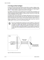
Страница 20: ...Camera Interface 2 6 Basler L301kc DRAFT Figure 2 3 Camera Frame Grabber Interface...
Страница 102: ...Configuring the Camera 4 32 Basler L301kc DRAFT...
Страница 104: ...Mechanical Considerations 5 2 Basler L301kc DRAFT Figure 5 1 L301kc Mechanical Dimensions in mm...
Страница 116: ...Troubleshooting 6 10 Basler L301kc DRAFT...
Страница 118: ...Revision History ii Basler L301kc DRAFT...
Страница 120: ...Feedback iv Basler L301kc DRAFT...
Страница 124: ...Index viii Basler L301kc DRAFT...