1-2
BE1-50 General Information
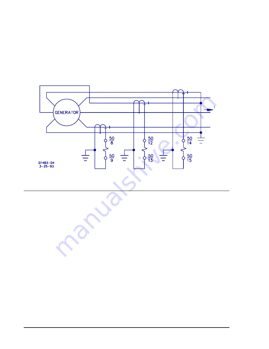
element (Figure 1-1a, d, e, f). The second method is called self-balancing differential protection (Figure 1-2).
In this application, the two leads of each phase of the protected motor or generator are passed through the
window of the same associated phase current transformer so that the resulting secondary current is zero
under normal operating conditions.
Combination With Other Protective Devices
Because BE1-50 relays can provide complete phase and ground fault protection in one unit (and with
independent settings for phase and ground), they are often used to supervise other relay functions. In
distance protection, BE1-50 relays can be used to prevent misoperation for light loading conditions by
requiring a minimum current level before enabling the distance relay. As a fault detector, they are
particularly effective because of their sensitivity, speed, and drop-out ratio.
Figure 1-2. Self-Balancing Differential Protection
MODEL AND STYLE NUMBER DESCRIPTION
BE1-50 Instantaneous Overcurrent Relays electrical characteristics and operational features are defined by
a combination of letters and numbers that make up its style number. The model number, together with the
style number, describe the options included in a specific device, and appear on the front panel, drawout
cradle, and inside the case assembly. Upon receipt of a relay, be sure to check the style number against
the requisition and the packing list to ensure that they agree.
Style number identification chart (Figure 1-3) defines the electrical characteristics and operational features
included in BE1-50 relays. For example, if the style number were J6J A1P J1E1F, the device would have
the following:
(J)
-
3-phase-and-neutral sensing
(6)
-
Phase sensing input range of 4.0 to 32 amperes.
(J)
-
Four normally open (N.O.) output relays.
(A1) -
Instantaneous timing.
(P)
-
Operating power derived from 125 Vdc or 100/120 Vac.
(J)
-
Four internally operated targets.
(1)
-
Push-to-energize outputs (pushbuttons).
(E)
-
Neutral sensing range of 0.25 to 2.0 amperes.
(1)
-
N.O. auxiliary output relay.
(F)
-
Semi-flush mounting.
Содержание BE1-50
Страница 1: ... 05647 6 10 07 14 056 06 0 175 18 4 744 06 4 Publication 9 1710 00 990 Revision C 11 98 ...
Страница 5: ...iv BE1 50 Introduction CONTENTS Continued SECTION 7 MANUAL CHANGE INFORMATION 7 1 Changes 7 1 ...
Страница 12: ...2 2 BE1 50 Human Machine Interface Figure 2 1 Location of Controls and Indicators ...
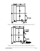
Страница 20: ...BE1 50 Installation 4 5 Figure 4 7 S1 Case Single Ended Panel Drilling Diagram Rear View ...
Страница 21: ...4 6 BE1 50 Installation Figure 4 8 S1 Case Double Ended Panel Drilling Diagram Rear View ...
Страница 22: ...BE1 50 Installation 4 7 Figure 4 9 Outline Dimensions Rear View ...
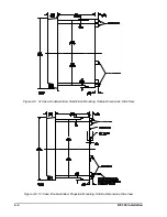
Страница 26: ...BE1 50 Installation 4 11 Figure 4 15 Typical Output Connections Sensing Input Type F and Output E or G ...
Страница 29: ...4 14 BE1 50 Installation Figure 4 18 Typical Internal Connections Single Phase Output E Option 3 5 ...


