background image

POLARIS COMFORT 

- for Zone 1/21 

POLARIS Touch Panel 5.7" / 10.4" / 12.1" 

Installation 


Technical data subject to change. 

06/2017 

EN   27/57 


6.6.3


Ethernet Terminal Assignment 

Configuration Ethernet 10BaseT 

Terminal  Interface 

Signal 

Remarks 

X13 

Ethernet 

RxD + 

100/10 BaseT  Receive      positive 

X14 

Ethernet 

RxD - 

100/10 BaseT  Receive      negative 

X15 

Ethernet 

TxD + 

100/10 BaseT  Transmit     positive 

X16 

Ethernet 

TxD - 

100/10 BaseT  Transmit     negative 

 
Assignment RJ45 plug for Ethernet to POLARIS Touch Panel terminal block 


Connection RJ45 

POLARIS 

PIN 

Signal 

Terminal 

TX+ 

X13 

TX- 

X14 

RX+ 

X15 

not used 


not used 


RX- 

X16 

not used 


not used 


PIN 1 

PIN 8 

Содержание POLARIS COMFORT Series

Страница 1: ...User Manual POLARIS COMFORT 5 7 up to 12 1 Zone 1 Zone 21...

Страница 2: ......

Страница 3: ...s 30 June 2017 Reservation Technical data subject to change without notice Changes errors and misprints may not be used as a basis for any claim for damages Content Pages English 1 57 GmbH Max Eyth St...

Страница 4: ...eristics POLARIS Touch Panel 5 7 11 4 1 2 Characteristics POLARIS Touch Panel 10 4 11 4 1 3 Characteristics POLARIS Touch Panel 12 1 12 4 2 Finger mouse trackball touchpad and joystick 12 4 2 1 Explos...

Страница 5: ...7 6 8 1 Voltage Supply DC Variants 37 6 8 2 Back up fuse 38 6 8 3 Interference suppression 38 6 8 4 Shielding 39 6 8 5 Connection of shielding 39 6 8 6 Examples of Shielding Connections 39 6 8 7 Ether...

Страница 6: ...blank...

Страница 7: ...e strict compliance with it is essential for safe installation and commissioning Accidents injuries and material damage can be avoided by circumspect handling and systematically following the instruct...

Страница 8: ...RTEC GmbH also apply The current versions of the datasheets operating instructions certificates and EU declarations of conformity can be downloaded from www bartec de or may be requested directly from...

Страница 9: ...th a dry cloth or cleaning it Do not open devices in a hazardous area The general statutory regulations or directives relating to safety at work accident prevention and environmental protection legisl...

Страница 10: ...1 6 5 Commissioning It must be checked that all components and documents are available before commissioning 1 7 Labelling test certificate and standards The device features an explosion protection la...

Страница 11: ...assembly commissioning operation and maintenance Structural modifications without our prior authorisation Inadequate monitoring of components that are subject to wear Repairs done incorrectly Disaste...

Страница 12: ...intuitive and comfortable operation are now available in the standard variant State of the art LED display technology ensures an optimum contrast event with a large viewing angle Illustration 1 POLARI...

Страница 13: ...A direct connection to the control or to the process control system is possible through Ethernet PROFIBUS DP or serial COM interfaces A finger mouse trackball touchpad and joystick are available as o...

Страница 14: ...ndards in accordance with EMC Directive 2014 34 EU IEC 60079 0 2011 Edition 6 IEC 60079 1 2007 04 Edition 6 IEC 60079 5 2015 Edition 4 IEC 60079 7 2006 07 Edition 4 IEC 60079 11 2011 Edition 6 IEC 600...

Страница 15: ...on Russia EAC TC RU C DE GB06 B 00334 Korea KTL 14 KB4BO 0258X India CCEs P261984 More test certificates www bartec de EU conformity RoHS Directive 2011 65 EU Standards in accordance with EMC Directiv...

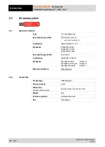
Страница 16: ...k 1 x Ex i for PS 2 for intrinsically safe mouse Interface optional only POLARIS Touch Panel 10 4 and 12 1 1 x Ex i Supply module for hand held scanner Display TFT colour display Supply voltage DC 24...

Страница 17: ...Max power consumption Pmax 30 W Dimensions width x height x depth 335 mm x 199 mm x 130 mm Wall cut out width x height 321 mm x 179 mm 0 5 mm Weight approx 10 kg 4 1 2 Characteristics POLARIS Touch Pa...

Страница 18: ...keys able to be labelled with LEDs Max power consumption Pmax 35 W Dimensions width x height x depth 440 mm x 275 mm x 130 mm Wall cut out width x height 425 mm x 255 mm 0 5 mm Weight approx 18 kg 4...

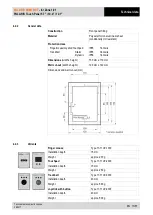
Страница 19: ...all Static Dynamic IP65 front site IP65 front site IP56 front site Dimensions width x height 130 mm x 170 mm Wall cut out width x height 100 mm x 140 mm Dimensions and wall cut out mm 4 2 3 Variants F...

Страница 20: ...5 ATEX 1117 X Standards EN 60079 0 2009 EN 60079 11 2012 EN 60079 31 2009 Ex protection type IECEx Ex ib IIC T4 Certification IECEx IBE 11 0007X Standards IEC 60079 0 2007 Edition 5 IEC 60079 11 2011...

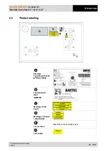
Страница 21: ...data Technical data subject to change 06 2017 EN 15 57 4 4 Product labelling Example Type label with label ATEX and IECEx Type label with label INMETRO Warnings on the device Warning on terminal comp...

Страница 22: ...anty provisions of BARTEC GmbH CAUTION This device is heavy 10 18 kg There is a risk of injury if it is lifted or moved incorrectly You will need help from others when transporting it 5 2 Intermediate...

Страница 23: ...IS termination 1 hey key 2 5 mm compartments 1 x slotted screwdriver POLARIS PE connection 1 x ring spanner 7 mm 5 4 1 Installation options The POLARIS can be installed directly in Enclosures Switch c...

Страница 24: ...to 50 C or from 20 C to 50 C and a relative air humidity of from 5 to 95 without condensation 6 1 Requirements The place where the POLARIS is installed must have sufficient mechanical stability fasten...

Страница 25: ...onnel i e trained skilled specialists will have the necessary specialised know how to be able to perform all the mechanical work Familiarity with and the technically perfect implementation of the safe...

Страница 26: ...ection Class IP65 POLARIS BASIC 5 7 05 0205 0006 POLARIS BASIC 10 4 05 0205 0008 POLARIS BASIC 12 1 05 0205 0007 Fit the reinforcement frame Illustration 7 Minimum installation depth and mounting rein...

Страница 27: ...g concrete must be selected for securing the load bearing system The structural stability of the wall or floor must be able to bear 4 times the weight of the POLARIS as system solution The support arm...

Страница 28: ...7 10 4 12 1 EN 22 57 Technical data subject to change 06 2017 6 2 3 Floor mounting stainless steel enclosure Illustration 8 Base drilling template base plate 6 2 4 Wall mounting Stainless steel enclo...

Страница 29: ...installation of the intrinsically safe circuits The safety and accident prevention regulations applicable to the respective individual case must be observed Devices must be properly installed first b...

Страница 30: ...re Do not open the locking screw DANGER Non certified cable glands and non sealed cable entries endanger the IP protection and accordingly the protection against explosions There is a risk of fatal in...

Страница 31: ...tor connections against self loosening Stainless steel enclosure Attach equipotential bonding to the enclosure All moving parts must be earthed Secure PE conductor connections against self loosening W...

Страница 32: ...that complies with the current version of the approval The assembly instructions and installation conditions for the cable glands must be observed Tightening torque oft he cable glands Torque Connecti...

Страница 33: ...Signal Remarks X13 Ethernet RxD 100 10 BaseT Receive positive X14 Ethernet RxD 100 10 BaseT Receive negative X15 Ethernet TxD 100 10 BaseT Transmit positive X16 Ethernet TxD 100 10 BaseT Transmit nega...

Страница 34: ...xD Receiving cable Input X23 Interface COM 1 TxD B TxD Transmission cable Output X24 Interface COM 1 TxD A TxD Transmission cable Output X25 Interface COM 1 RxD B RxD Receiving cable Output X26 Interf...

Страница 35: ...twork A1 A2 X21 Interface COM 1 Termination B1 Bridge for terminating network B1 B2 X22 Interface COM 1 Termination A1 Bridge for terminating network A1 A2 X23 Interface COM 1 Out B Signal B Output X2...

Страница 36: ...1 20 mA Signal power source for receiver X23 Interface COM 1 GND Signal ground for transmitter X24 Interface COM 1 Tx Emitter X25 Interface COM 1 Tx Collector X26 Interface COM 1 20 mA Signal power so...

Страница 37: ...ted X18 Not connected X19 Not connected X20 Not connected X21 Not connected X22 Not connected X23 Not connected X24 Interface COM 1 RxD Receive X25 Interface COM 1 TxD Transmit X26 Interface COM 1 GND...

Страница 38: ...able as follows Touch Panel USB connection Colour Function X23 1 RD VCC 5 V X26 4 BK GND X25 3 GN Data X24 2 WH Data The maximum length of a lead should not exceed 2 m Maximum current 500 mA 6 6 9 Int...

Страница 39: ...put device to the POLARIS optional Do not connect the keyboard mouse trackball touchpad joystick or the hand scanner while the power supply is active PS 2 for input devices Terminal Interface Colour S...

Страница 40: ...e Inline E258105 AWM STYLE 2725 80 C 30V VW 1 28AWGX1P 24AWGX2C USB 2 0 High speed cable 6 7 3 Ex d socket optional DANGER Live plug in connections Risk of fatal injury if opened in an explosive atmos...

Страница 41: ...mH The BCS 160ex hand scanner series can only be used with the original connection cable from BARTEC Not compatible is the hand scanner BCS 160ex with 1D72D Imager Typ 17 21BA M31S I0000000 Connectio...

Страница 42: ...e 100 MBit s Permissible ambient temperatures Storage transport Operation 20 C bis 80 C 0 C bis 55 C Multi mode Range Fibre type Min transmitting power Min sensitivity Wave length Plug connector up to...

Страница 43: ...on may neither exceed nor drop below DC 24 V 10 Observe the voltage drop on the supply cable and correct if necessary The voltage drop in the DC variant of the supply line is calculated with the follo...

Страница 44: ...e The internal fuse can only be replaced by BARTEC Back up fuse DC 2 5 A slow blowing The I2 value is to be observed for other versions of the fuses 6 8 3 Interference suppression Certain basic measur...

Страница 45: ...o the metal casing of the sub D plug The plug casing of some controllers is not always well connected to earth In such cases it may prove advantageous to insulate the shielding from the sub D plug of...

Страница 46: ...Connection of the shielding at one end only is recommended when there is inadequate equipotential bonding or none at all In such cases an electrically isolated power supply unit must be used Before t...

Страница 47: ...e is present and that the power supply has been turned off POLARIS COMFORT Has the reinforcement frame between the bracket and enclosure been inserted Is there no damage to seals cable connections or...

Страница 48: ...lay The changes that are made are not available after rebooting Partition D Is not protected by EWF Write access to Partition D is possible at any time The data is still available after a reboot Data...

Страница 49: ...d 3 Confirm with OK 4 Enter the ewfmgr c enable command line into the command window 5 Confirm with the Enter key 6 Reboot the system 7 EWF is active 7 2 2 Network Ethernet Setup Requirements Network...

Страница 50: ...tocol figure 2 the function is started Figure 1 Figure 2 The chart figure 3 appears when the network and a DHCP server are available Configuration example figure 4 when no DHCP server is available Fig...

Страница 51: ...t Alt Left Alt Left Alt Left S18 Ctrl Ctrl Left Ctrl Left Ctrl Left Ctrl Left S19 7 ABC Num 7 7 Num 7 Num 7 S20 8 DEF Num 8 8 Num 8 Num 8 S21 9 GHI Num 9 9 Num 9 Num 9 S22 4 JKL Num 4 4 Num 4 Num 4 S2...

Страница 52: ...F5 e Ctrl F1 Right Alt F5 S49 S6 Shift F6 f Ctrl F2 Right Alt F6 S50 S7 Shift F7 g Ctrl F3 Right Alt F7 S51 S8 Shift F8 h Ctrl F4 Right Alt F8 S52 S9 Shift F9 i Ctrl F5 Right Alt F9 S53 S10 Shift F10...

Страница 53: ...2 Autostart Menu Download Once the operating voltage has been applied the POLARIS Touch Panel boots in XP Embedded The user administrator is logged on automatically with a password 22021963 an input...

Страница 54: ...e BMS Graf pro Start the FTP server Once the FTP server has started after switching on data can be transmitted at any time without the need to reboot the FTP server It is only necessary to reboot the...

Страница 55: ...8 3 2 Backup We expressly point out that it is the user s responsibility to make a backup of the POLARIS and all its functions We strongly recommend saving such a POLARIS backup on a recovery stick 8...

Страница 56: ...Return to manufacturer Windows doesn t start Faults in the operating system Install the operating system again Recovery stick There are always stripes on the display Display defective or CPU does not...

Страница 57: ...tions DANGER Prevent electrostatic charging in hazardous potentially explosive areas There is a risk of a fatal injury in an explosive atmosphere Take devices out of hazardous areas before wiping them...

Страница 58: ...ded as professional electric devices for business use only referred to as B2B devices under the WEEE Directive The WEEE directive sets the framework for waste electric and electronic equipment handlin...

Страница 59: ...71VZ 2000 Touchpad 17 71VZ 3000 Joystick with button 17 71V2 9000 Connection cable for mouse 1 8 m 05 0068 0163 3 0 m 03 0068 0204 for trackball joystick 1 8 m 03 0068 0172 3 0 m 05 0068 0205 for touc...

Страница 60: ...bers POLARIS COMFORT for Zone 1 21 POLARIS Touch Panel 5 7 10 4 12 1 EN 54 57 Technical data subject to change 06 2017 14 Order numbers POLARIS Touch Panel 5 7 POLARIS Touch Panel 10 4 POLARIS Touch P...

Страница 61: ...POLARIS COMFORT for Zone 1 21 POLARIS Touch Panel 5 7 10 4 12 1 Additional infromation Technical data subject to change 06 2017 EN 55 57 15 Additional information...

Страница 62: ...Declaration of conformity POLARIS COMFORT for Zone 1 21 POLARIS Touch Panel 5 7 10 4 12 1 EN 56 57 Technical data subject to change 06 2017 16 Declaration of conformity...

Страница 63: ...POLARIS COMFORT for Zone 1 21 POLARIS Touch Panel 5 7 10 4 12 1 Declaration of conformity Technical data subject to change 06 2017 EN 57 57 All certificates see www bartec de...

Страница 64: ...Your partner for safety technology Challenge us BARTEC GmbH Max Eyth Str 16 97980 Bad Mergentheim Germany Phone 49 7931 597 0 info bartec de www bartec de EN_11 71V1 7D0011 07 2017 Automation 357370...

Отзывы: