WAM Arm – User’s Manual
www.barrett.com
© 2008 Barrett Technology®, Inc.
Document: D1001, Version: AH.00
56 of 80
9 Theory of Operation
9.1 Electronic
Architecture
Figure 33 – WAM System Components
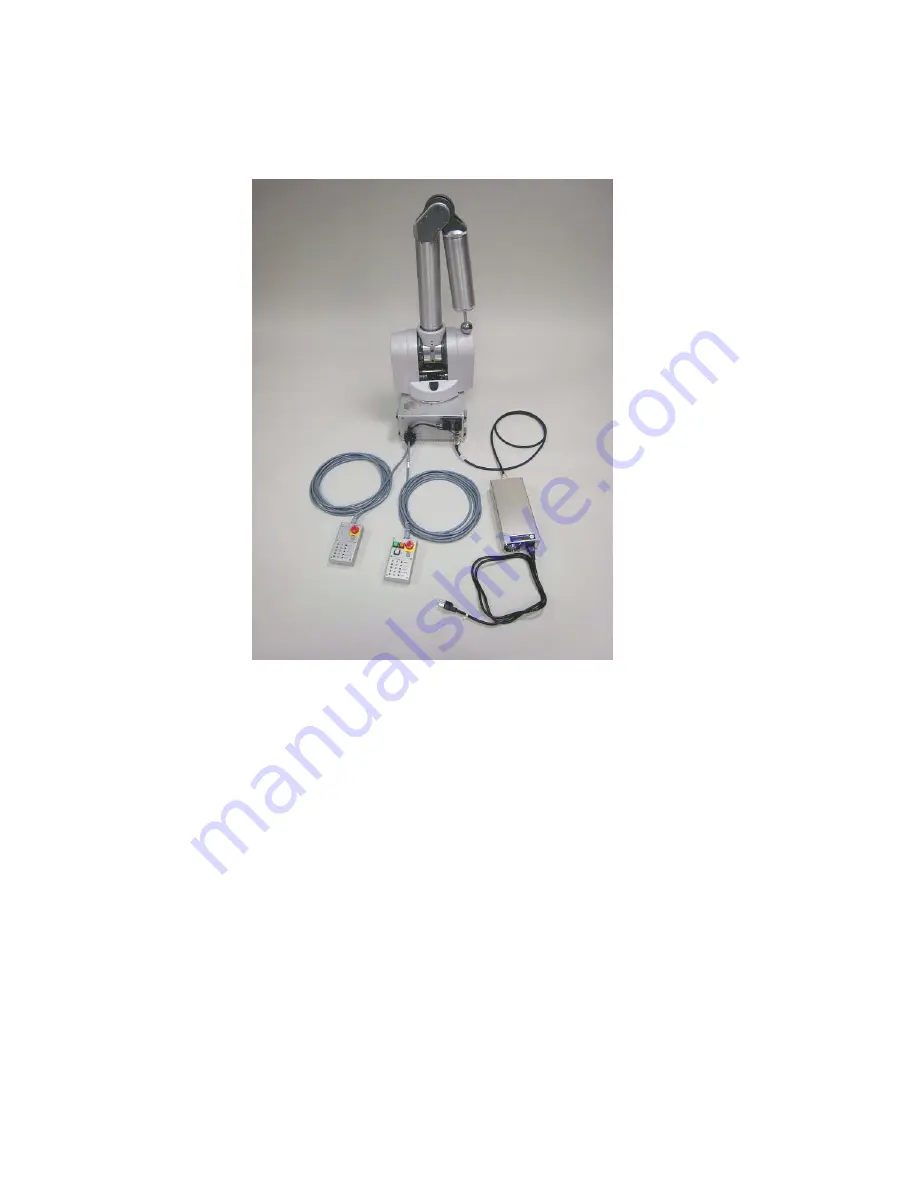
The following major components are part of your WAM system:
•
The WAM Arm robot with embedded motor controllers (Pucks™).
•
An internal PC/104 form-factor computer loaded with the Linux operating system.
•
An internal safety system.
•
An external power supply for the WAM.
•
A Control Pendant and Display Pendant.
•
(Optional) an external PC loaded with Linux, a CAN communications card, a CANbus cable
Figure 33 shows a schematic of the WAM system subcomponents that are important to the WAM
programmer. The power supply is used with AC outlets, as specified in Section 3.6.1. It provides
48 VDC to the safety module which in turn provides the necessary voltage to the motors and the
internal PC.
The internal computer is responsible for closing the control loop and providing high-level
command of the WAM system. The control loop is the repeated reading of motor angles and
commanding of motor torques to provide a smooth and safe motion of the WAM Arm robot.
High-level command is deciding when and where to move to robot and providing an interface for
the user of the WAM system to accomplish their task.


