WAM Arm – User’s Manual
www.barrett.com
© 2008 Barrett Technology®, Inc.
Document: D1001, Version: AH.00
25 of 80
1.
If you are using Ethernet or CANbus communication, verify that the appropriate cable is
plugged into the desired communications port.
2.
Confirm that the WAM safety board is properly configured for the communication option
you have chosen.
3.
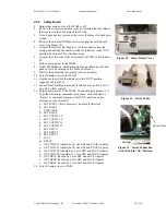
Verify that the Control and Display Pendant cords are plugged into the correct sockets on
the back of the WAM.
4.
If you are using an AC power source, verify that the AC Line Cord is plugged into a valid
power source (see Appendix B) and into the power outlet on the back of the Power
Supply.
5.
If you are using the external WAM PC, verify that the computer line cord is plugged into
a power source and into the power outlet on the back of the computer.
Once the previous steps are complete, your WAM is ready for start-up. Power up the system
according to the instructions below:
1.
Turn on the power source to the WAM.
2.
If using the external PC, turn on the power source to the external PC.
3.
If using a personal computer to control the WAM, connect to the WAM PC (From a *nix
PC, use ssh -l root <wam-ip-address>, or from a Windows PC, use the free PuTTY ssh
client to connect – Putty can be downloaded at http://www.putty.nl/download.html –
username = root, password = WAM).
4.
Launch control program (btclient/src/btdiag/btdiag is standard)
5.
Make sure both E-Stop buttons are reset (up). If they are not, rotate them one quarter of a
turn clockwise.
6.
Press <Shift+Reset/Idle> on the control pendant.
7.
Place the WAM into its home position (see Appendix C for details on the home position).
8.
Press <Shift+Activate> on the control pendant.
The WAM is now ready for use.
3.8 Code
Examples
In the code examples, the PC closes a 500 Hz position/torque control loop with the WAM over the
CAN bus. The PC asks the motor controllers for their present positions, converts the received
encoder counts into joint angles, calculates the desired joint torques, converts these into motor
torque commands, then sends out the calculated torques to the motors. All force or position control
is calculated on the PC and converted to motor torques as a final step – the WAM itself is entirely
motor torque controlled. For a source code example of this process, see the WAMControlThread()
function in src/btwam/btwam.c.
These examples are preloaded onto the WAM PC to help demonstrate the capabilities of the
WAM Arm and the functionality of the WAM library. The examples and their functions are as
follows:
Example 1:
A minimalist program for the WAM that prints out the position of the end
point of the WAM.
Example 2:
A minimalist program for the WAM that calculates and sends gravity
compensation torques.
Example 3:
This program demonstrates the datalogging, timing, and WAM control loop
callback functions of the library.
Example 4:
Demonstrates haptic (force-feedback) interaction with the WAM.
Example 5:
Demonstrates the MoveWAM() function in joint space and Cartesian space.
Example 7: Opens the serial port at the end of the outer link, initializes the BarrettHand,
and makes the Hand move.


