WAM Arm – User’s Manual
www.barrett.com
© 2008 Barrett Technology®, Inc.
Document: D1001, Version: AH.00
22 of 80
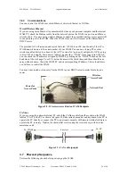
3.5 Safety Board Settings
For different methods of communication (and different connections to the
BarrettHand™, if attached) certain switches must be changed. To access
these switches, turn off the WAM™, remove the 4-mm Hex screw in the
upper-left corner of the back of the WAM™ (Figure 24), unlatch the base
cover, and rotate the back plate of the WAM™ out so that it is in a
horizontal position. (Figure 25). If you are facing the WAM™ from the
back, the relevant switches will be on the lower-left corner (see Figure
23). If a switch is “out” the raised part of that pin is on the side closest to
the edge of the safety board, and the opposite is true if the switch is “in”.
Table 1 – WAM Communication Settings
Mode
*
:
Switch 1-2
Switch 1-3
Ethernet IN
IN
CAN (from External PC)
OUT
OUT
Table 2 – Hand Communication and Power Settings
Modes
*
:
Switch 2
Switch 1-1
Internal Power & Communications
IN
IN
External Power & Communications
OUT
OUT
Figure 23 – Safety Board
Switches
*
Contact Barrett for additional modes of operation, for example: running 2 WAMs off of a single
PC-104, or running a BarrettHand off of internal power with external (non-PC-104)
communications.
Switch 1-1
(“in”)
Switch 1-2
(“in”)
Switch 1-3
(“in”)
Switch 2
(“in”)
Figure 24 – WAM Backplate
Figure 25 – Safety Board Cover
4 mm Hex
screw


