9
8.
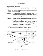
Recorder output and alarm output devices may be installed on the tem-
perature controller (refer to Figure 5). The 4/20mA recorder output is
designed for a left positive (+) and a right negative (-) connection. Alarm
output is designed for a left–NO (normally open), center–COM (com-
mon), and right–NC (normally closed) connector.
SETUP PROCEDURE
NOTES:
a. At any time during the setup procedure, you may return to
the previous screen by pressing and holding down the LEFT
arrow key and then pressing the MENU key.
b. For experienced operators, a flow chart may be used for set-
up. Refer to Appendix A.
c. The setup mode can only be entered when the Temperature
Controller is stopped.
1.
Set the ON/OFF switch on the rear panel to ON. The LEDs will light and
all segments will light temporarily as a check of the display.
2.
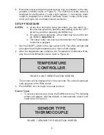
After the diagnostics are complete, the Temperature Controller will dis-
play the unit identification screen (refer to Figure 6).
TEMPERATURE
CONTROLLER
FIGURE 6. UNIT IDENTIFICATION SCREEN
This screen will be displayed for a few seconds. The unit will automati-
cally progress to the RUN screen.
3.
Press MENU once to begin the setup process.
Sensor Types
1.
To select a sensor type, press the DOWN arrow key. The following
screen will appear, with the default, or last selected, sensor indi-
cated (refer to Figure 7).
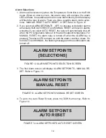
SENSOR TYPE
THERMOCOUPLE
FIGURE 7. SENSOR TYPE SELECTION SCREEN

