BARIX AG
| Ringstrasse 15 A | CH-8600 Dübendorf | T + 41 43 43322 11 | www.barix.com
Page 9
/
10
1.
2.
3.
4.
5.
9 Hardware functionality
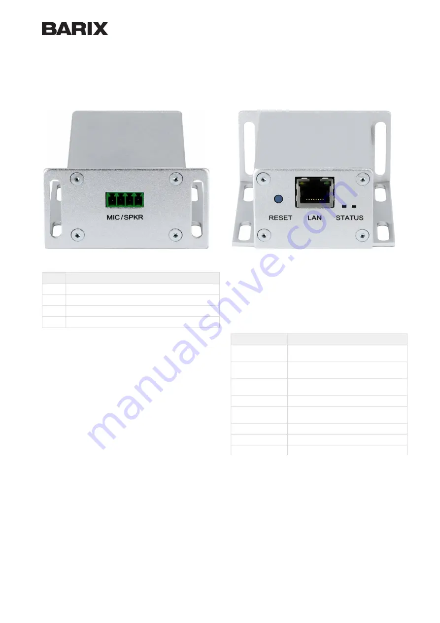
Front view
Rear view
MIC / SPKR
Pin
Description
1
MIC IN
2
AGND
3
SPKR -
4
SPKR +
Please note that the MIC Input is for further use and does not
have any functionality with the current Firmware.
RESET Button
A brief press of the button (3 seconds) will reboot the device.
Holding the reset button pressed for approximately 10 seconds
will reset the device and restore the factory default settings
when the button is released.
LAN - Ethernet (RJ45)
Pin
Description
1
TX + (Transmit data)
V+ mode A
2
TX - (Transmit data)
V+ mode A
3
RX + (Receive data)
V- mode A
4, 5
V+ mode B
6
RX – (Receive data)
V- mode A
7, 8
V- mode B
Left LED Yellow
Activity
Left LED Green
Link / Speed (Blinking)
SYSTEM STATUS LED
Dual Color green/red System Status LED.
Red blinking fast: early startup
Red blinking slow: system booting
Yellow blinking: System in Rescue Mode
Orange / Yellow blinking: Downloading / Installing Firmware
Green solid: system ready


