Bard WG421 Скачать руководство пользователя страница 4

Manual 2100-365
Page  1

Getting Other Information and Publications

For more information, contact these
publishers:

ACCA

Air Conditioning Contractors of America

1712 New Hampshire Avenue, NW
Washington, DC 20009
Telephone: (202) 483-9370

ANSI

American National Standards Institute

11 West Street, 13th Floor
New York, NY 10036
Telephone: (212) 642-4900
Fax: (212) 302-1286

ASHRAE American Society of Heating Refrigerating,

and Air Conditioning Engineers, Inc.

1791 Tullie Circle, NE.
Atlanta, GA 30329-2305
Telephone: (404) 636-8400
Fax: (404) 321-5478

NFPA

National Fire Protection Association

Batterymarch Park
P.O. Box 9101
Quincy, MA 02269-9901
Telephone: (800) 344-3555
Fax: (617) 984-7057

CSA

Canadian Standards Association

178 Rexdale Boulevard
Rexdale, Ontario
Canada.  M9W 1R3
Telephone:  (416) 447-4044

COPYRIGHT AUGUST, 2000

BARD MANUFACTURING COMPANY

BRYAN, OHIO  43506  USA

Manufactured under the following U.S. patent numbers:

5,485,878;  5,002,116;  4,924,934;  4,875,520;  4,4825,936;  4,432,409

These publications can help you install the furnace.
You can usually find these at your local library or
purchase them directly from the publisher.  Be sure to
consult current edition of each standard.

National Fuel Gas Code ....... ANSI Z223.1 / NFPA 54

National Electrical Code .................. ANSI / NFPA 70

Standard for the Installation ......... ANSI / NFPA 90A
of Air Conditioning and
Ventilating Systems

Standard for Warm Air .................. ANSI / NFPA 90B
Heating and Air Conditioning
Systems

Standard for Chimneys, .............................. NFPA 211
Fireplaces, Vents, and Solid
Fuel Burning Appliances

Load Calculation for ......................... ACCA Manual J
Residential Winter and
Summer Air Conditioning

Duct Design for Residential ............ ACCA Manual D
Winter and Winter Air Conditioning
and Equipment Selection

Canadian Electrical Code .......................... CSA C22.1

Содержание WG421

Страница 1: ...RESPONSIBILITY OF INSTALLER TO KNOW AND UNDERSTAND ALL OF THESE REQUIREMENTS FAILURE TO DO SO COULD CREATE A HAZARD RESULTING IN PROPERTY DAMAGE BODILY INJURY OR DEATH INSTALLATION INSTRUCTIONS WG SER...

Страница 2: ...hermostats 16 18 Gas Supply Piping 19 19 Manifold Pressure Adjustment 20 20 Checking Gas Input Rate 20 21 Standard Orifice Sizing High Altitude Derate 21 22 Conversion of Gas Input BTUH From High to L...

Страница 3: ...Electronic Blower Control 29 Figure 17 Furnace Control Board Blower Control 30 Figure 18 460V Blower Motor Wiring Options 31 Figure 19 Fan Blade 37 Figure 20 Low NOx Insert 37 TABLES Table 1 Specifica...

Страница 4: ...Telephone 416 447 4044 COPYRIGHT AUGUST 2000 BARD MANUFACTURING COMPANY BRYAN OHIO 43506 USA Manufactured under the following U S patent numbers 5 485 878 5 002 116 4 924 934 4 875 520 4 4825 936 4 43...

Страница 5: ...t l o V 0 3 2 r o t a l i t n e V y r e v o c e R y g r e n E R 5 A V R E G W t l o V 0 6 4 r o t a l i t n e V y r e v o c e R y g r e n E R 5 C V R E G W VENTILATION OPTIONS 1 Low ambient control is...

Страница 6: ...erant system is completely assembled and charged All internal wiring is complete These instructions and any instructions packaged with any separate equipment required to make up the entire heating coo...

Страница 7: ...0 3 2 0 6 4 s p m A d a o L d e t a R 9 1 5 7 1 3 1 2 1 6 5 1 2 1 2 3 1 5 2 1 2 6 0 3 7 2 5 9 1 7 1 9 t n e r r u C n o i t c e l e S t i u c r i C h c n a r B 9 1 3 1 6 2 2 3 1 4 6 0 3 5 9 1 9 s p m...

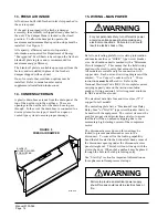
Страница 8: ...Manual 2100 365 Page 5 MIS 1352 FIGURE 1 UNIT DIMENSIONS...

Страница 9: ...in the absence of specific recommendations from the local authority having jurisdiction equipment ratings shall be reduced as specified in Section 18 5 TRANSPORTATION DAMAGE All units are packed secu...

Страница 10: ...e Figures 6 and 7 for details 3 Locate and mark lag bolt locations and bottom mounting bracket location 4 Mount bottom mounting bracket 5 Hook top rain flashing under back bend of top Top rain flashin...

Страница 11: ...Manual 2100 365 Page 8 FIGURE 2 VENT TERMINAL AND COMBUSTION AIR INTAKE MIS 1469 MIS 1449 FIGURE 3 INTERNAL FILTER ACCESS THROUGH UPPER SERVICE DOOR...

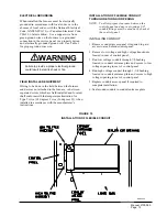
Страница 12: ...Manual 2100 365 Page 9 FIGURE 4 MOUNTING INSTRUCTIONS MIS 1472...

Страница 13: ...le materials This is required for the first three 3 feet of ducting It is important to insure that the one 1 inch minimum spacing is maintained at all points Failure to do this could result in overhea...

Страница 14: ...Manual 2100 365 Page 11 FIGURE 6 WALL MOUNTING INSTRUCTIONS FIGURE 7 WALL MOUNTING INSTRUCTIONS MIS 1475 MIS 1476...

Страница 15: ...Manual 2100 365 Page 12 FIGURE 8 COMMON WALL MOUNTING INSTALLATIONS MIS 1474...

Страница 16: ...r previous conditions of use 7 If improper venting is observed during any of the above tests the venting system must be corrected 9 CLEARANCES Minimum clearances as specified in Table 2 must be mainta...

Страница 17: ...imum Circuit Ampacity This means that the field wiring used must be sized to carry that amount of current All models are suitable only for connection with copper wire Each unit and or wiring diagram w...

Страница 18: ...with the manufacturer s instructions INSTALLATION OF FLEXIBLE CONDUIT THROUGH RETURN AIR OPENING NOTE To allow proper clearance between the control panel and any vent options 90 conduit fittings must...

Страница 19: ...m e t s y S 5 3 0 3 0 4 8 0 8 5 9 F 1 e g a t s 2 t a e h e g a t s 2 o o c l e l b a m m a r g o r P c i n o r t c e l E 3 4 0 3 0 4 8 0 0 2 M C t a e h e g a t s 1 l o o c e g a t s 1 o t u a n o n...

Страница 20: ...Manual 2100 365 Page 17 FIGURE 11 LOW VOLTAGE WIRING MIS 1162...

Страница 21: ...Manual 2100 365 Page 18 FIGURE 12 GAS PIPE CONNECTION MIS 1478...

Страница 22: ...1 9 1 f o h t g n e L t e e F e p i P e z i S e p i P t u p n I r u o H r e p U T B y t i c a p a C e p i P 2 1 4 3 1 4 1 1 0 1 0 0 0 2 3 1 0 0 0 8 7 2 0 0 0 0 2 5 0 0 0 0 5 0 1 0 2 0 0 0 2 9 0 0 0 0...

Страница 23: ...pingement or overheating of heat exchanger NOTE For natural gas if gas flow rate can t be properly set within these pressure ranges then you must change main burner orifices to obtain proper gas flow...

Страница 24: ...s to consume two cubic feet of gas If dial is one half cubic foot per revolution measure time for four revolutions If dial is one cubic foot per revolution measure time for two revolutions If dial is...

Страница 25: ...2 5 4 2 5 4 2 0 4 2 5 3 2 0 3 2 5 2 2 0 2 2 5 1 2 9 9 8 0 8 8 0 5 2 0 4 2 5 3 2 0 3 2 0 3 2 5 2 2 0 2 2 5 1 2 0 1 2 9 4 9 0 0 9 0 4 2 0 3 2 0 3 2 5 2 2 0 2 2 0 2 2 5 1 2 0 1 2 5 0 2 9 9 9 0 5 9 5 3 2...

Страница 26: ...onditions 30 00 inches Mercury 60F saturated NOTE 2 40 Standard factory installed orifice size 2 30 is shipped with the unit for field installed optional 10 derate All orifice sizes not shown with a b...

Страница 27: ...de the temperature rise range specified on rating plate check duct system design with a qualified heating engineer It may be necessary to re size the duct work Recheck air temperature rise after revis...

Страница 28: ...rgize and go into a soft lockout Regardless the state of the low pressure switch the contactor will reenergize after the delay on make time delay has expired If the ALARM OUTPUT Alarm terminal is outp...

Страница 29: ...Manual 2100 365 Page 26 26 LIGHTING AND SHUTDOWN INSTRUCTIONS FIGURE 14 INSTRUCTION LABEL...

Страница 30: ...at exchanger warms up There should be no change in the size or shape of the flame If there is any wavering or blowing of the flame on blower start up it is an indication of a possible leak in the heat...

Страница 31: ...ations Inspect venting system Make sure system has no holes is physically sound and free from obstructions c Make sure the supply and return air flange sleeves or duct work are securely fastened to un...

Страница 32: ...h T d e z i g r e n e s i l a n i m r e t W a a a a a d e z i g r e n e s i r e w o l b r i a n o i t s u b m o C d e h s i l b a t s e s i w o l f r i A s e k a m h c t i w s g n i v o r p r i A d e...

Страница 33: ...g may be required to be removed or added 32 INDOOR BLOWER OPERATION All models have three speed direct drive blower motors If supply and return ducts are connected to the unit the ducts must be of ade...

Страница 34: ...Manual 2100 365 Page 31 FIGURE 18 460 VOLT BLOWER MOTOR WIRING OPTIONS MIS 1487 A B C...

Страница 35: ...1 0 3 4 1 0 3 1 1 P S E s e h c n I Hs O E D O M G N I L O O C N A F L A U N A M d n a E D O M G N I T A E H l i o C t e W U T B 0 0 0 0 0 1 t u p n I U T B 0 0 0 0 9 h g i H m u i d e M w o L h g i...

Страница 36: ...4 3 1 0 3 4 1 0 3 4 1 0 3 1 1 P S E s e h c n I Hs O E D O M G N I L O O C N A F L A U N A M d n a E D O M G N I T A E H l i o C t e W U T B 0 0 0 0 0 1 t u p n I U T B 0 0 0 0 9 h g i H m u i d e M...

Страница 37: ...1 0 3 4 1 0 3 4 1 0 3 1 1 P S E s e h c n I Hs O E D O M G N I L O O C N A F L A U N A M d n a E D O M G N I T A E H l i o C t e W U T B 0 0 0 0 0 1 t u p n I U T B 0 0 0 0 9 h g i H m u i d e M w o...

Страница 38: ...t i w s t u o l l o r n a F l a u n a M n o f I y a l e d f f o d e t c e l e s e h t r o f e t a r e p o l l i w r e w o l b r i a t r o f m o c e h t e t a r e p o o t e u n i t n o c l l i w r e w...

Страница 39: ...5 2 5 7 7 6 2 6 7 2 8 2 8 7 0 0 3 9 7 5 1 3 1 8 2 3 3 B D g e d 0 8 B W g e d 7 6 e d i S w o L e d i S h g i H 2 7 1 1 2 4 7 6 2 2 6 7 2 4 2 8 7 7 5 2 0 8 4 7 2 1 8 0 9 2 4 8 7 0 3 5 8 3 2 3 7 8 1 4...

Страница 40: ...information FIGURE 19 FAN BLADE TABLE 15 FAN BLADE DIMENSION l e d o M A n o i s n e m i D 1 2 4 G W 1 1 8 4 G W 1 1 0 6 G W 1 Any service work requiring removal or adjustment in the fan and or motor...

Страница 41: ...Manual 2100 365 Page 38...

Страница 42: ...Manual 2100 365 Page 39...

Страница 43: ...Manual 2100 365 Page 40...

Страница 44: ...Manual 2100 365 Page 41...

Страница 45: ...Manual 2100 365 Page 42...

Страница 46: ...Manual 2100 365 Page 43...

Страница 47: ...Manual 2100 365 Page 44...

Страница 48: ...Manual 2100 365 Page 45...

Страница 49: ...Manual 2100 365 Page 46...

Страница 50: ...Manual 2100 365 Page 47...

Страница 51: ...Manual 2100 365 Page 48...

Страница 52: ...Manual 2100 365 Page 49...

Отзывы: