Manual 2100-365
Page 36
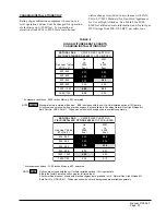
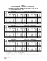
33. PRESSURE SERVICE PORTS
High and low pressure service ports are installed on all
units so that the system operating pressures can be
observed. Table 13 outlines expected pressures at
various indoor and outdoor temperatures.
34. REFRIGERANT CHARGE
The correct system R-22 charge is shown on the unit
rating plate. Optimum unit performance will occur
with a refrigerant charge resulting in a suction line
temperature (6” from compressor) as shown in
Table 14.
The suction line temperatures in Table 14 are based
upon 80 degrees F dry bulb / 67 degree wet bulb
(50% R.H.) temperature and rated airflow across the
evaporator during cooling cycle.
Total system charge for these models can be found in
Table 1.
TABLE 14
REFRIGERANT CHARGE
l
e
d
o
M
d
e
t
a
R
w
o
l
f
r
i
A
F
.
g
e
D
5
9
.
p
m
e
T
D
O
F
.
g
e
D
2
8
.
p
m
e
T
D
O
1
2
4
G
W
0
0
3
1
7
5
-
5
5
8
6
-
6
6
1
8
4
G
W
0
5
5
1
6
5
-
4
5
6
6
-
4
6
1
0
6
G
W
0
5
6
1
8
5
-
6
5
8
6
-
6
6
l
e
d
o
M
r
i
A
n
r
u
t
e
R
e
r
u
t
a
r
e
p
m
e
T
e
r
u
s
s
e
r
P
5
7
0
8
5
8
0
9
5
9
0
0
1
5
0
1
0
1
1
5
1
1
1
2
4
G
W
B
D
.
g
e
d
5
7
B
W
.
g
e
d
2
6
e
d
i
S
w
o
L
e
d
i
S
h
g
i
H
6
6
6
0
2
9
6
1
2
2
1
7
6
3
2
3
7
1
5
2
5
7
7
6
2
6
7
2
8
2
8
7
0
0
3
9
7
5
1
3
1
8
2
3
3
B
D
.
g
e
d
0
8
B
W
.
g
e
d
7
6
e
d
i
S
w
o
L
e
d
i
S
h
g
i
H
2
7
1
1
2
4
7
6
2
2
6
7
2
4
2
8
7
7
5
2
0
8
4
7
2
1
8
0
9
2
4
8
7
0
3
5
8
3
2
3
7
8
1
4
3
B
D
.
g
e
d
5
8
B
W
.
g
e
d
2
7
e
d
i
S
w
o
L
e
d
i
S
h
g
i
H
8
7
9
1
2
0
8
4
3
2
2
8
0
5
2
4
8
6
6
2
6
8
3
8
2
7
8
9
9
2
9
8
6
1
3
1
9
4
3
3
3
9
2
5
3
1
8
4
G
W
B
D
.
g
e
d
5
7
B
W
.
g
e
d
2
6
e
d
i
S
w
o
L
e
d
i
S
h
g
i
H
9
6
9
9
1
0
7
4
1
2
2
7
9
2
2
3
7
4
4
2
4
7
1
6
2
5
7
8
7
2
6
7
4
9
2
7
7
2
1
3
9
7
1
3
3
B
D
.
g
e
d
0
8
B
W
.
g
e
d
7
6
e
d
i
S
w
o
L
e
d
i
S
h
g
i
H
4
7
5
0
2
5
7
0
2
2
6
7
5
3
2
8
7
1
5
2
9
7
8
6
2
0
8
5
8
2
2
8
2
0
3
3
8
1
2
3
5
8
0
4
3
B
D
.
g
e
d
5
8
B
W
.
g
e
d
2
7
e
d
i
S
w
o
L
e
d
i
S
h
g
i
H
0
8
0
1
2
1
8
6
2
2
3
8
2
4
2
4
8
9
5
2
5
8
7
7
2
6
8
4
9
2
8
8
4
1
3
9
8
2
3
3
1
9
2
5
3
1
0
6
G
W
B
D
.
g
e
d
5
7
B
W
.
g
e
d
2
6
e
d
i
S
w
o
L
e
d
i
S
h
g
i
H
9
6
1
3
2
0
7
8
4
2
2
7
5
6
2
3
7
3
8
2
4
7
1
0
3
5
7
9
1
3
6
7
8
3
3
7
7
6
5
3
9
7
6
7
3
B
D
.
g
e
d
0
8
B
W
.
g
e
d
7
6
e
d
i
S
w
o
L
e
d
i
S
h
g
i
H
4
7
7
3
2
5
7
4
5
2
6
7
2
7
2
7
7
0
9
2
9
7
9
0
3
0
8
7
2
3
1
8
6
4
3
2
8
6
6
3
4
8
6
8
3
B
D
.
g
e
d
5
8
B
W
.
g
e
d
2
7
e
d
i
S
w
o
L
e
d
i
S
h
g
i
H
0
8
5
4
2
1
8
3
6
2
2
8
2
8
2
3
8
0
0
3
5
8
0
2
3
6
8
9
3
3
7
8
0
6
3
8
8
9
7
3
0
9
9
9
3
TABLE 13
COOLING PRESSURE TABLE
Low side pressure ± 2 PSIG
High side pressure ± 5 PSIG
Содержание WG421
Страница 8: ...Manual 2100 365 Page 5 MIS 1352 FIGURE 1 UNIT DIMENSIONS...
Страница 12: ...Manual 2100 365 Page 9 FIGURE 4 MOUNTING INSTRUCTIONS MIS 1472...
Страница 15: ...Manual 2100 365 Page 12 FIGURE 8 COMMON WALL MOUNTING INSTALLATIONS MIS 1474...
Страница 20: ...Manual 2100 365 Page 17 FIGURE 11 LOW VOLTAGE WIRING MIS 1162...
Страница 21: ...Manual 2100 365 Page 18 FIGURE 12 GAS PIPE CONNECTION MIS 1478...
Страница 29: ...Manual 2100 365 Page 26 26 LIGHTING AND SHUTDOWN INSTRUCTIONS FIGURE 14 INSTRUCTION LABEL...
Страница 34: ...Manual 2100 365 Page 31 FIGURE 18 460 VOLT BLOWER MOTOR WIRING OPTIONS MIS 1487 A B C...
Страница 41: ...Manual 2100 365 Page 38...
Страница 42: ...Manual 2100 365 Page 39...
Страница 43: ...Manual 2100 365 Page 40...
Страница 44: ...Manual 2100 365 Page 41...
Страница 45: ...Manual 2100 365 Page 42...
Страница 46: ...Manual 2100 365 Page 43...
Страница 47: ...Manual 2100 365 Page 44...
Страница 48: ...Manual 2100 365 Page 45...
Страница 49: ...Manual 2100 365 Page 46...
Страница 50: ...Manual 2100 365 Page 47...
Страница 51: ...Manual 2100 365 Page 48...
Страница 52: ...Manual 2100 365 Page 49...


