CONTENTS
FIGURES
Figure 1
Unit Dimensions ............................................ 5
Figure 2
Vent Terminal & Combustion
Air Intake ........................................................ 8
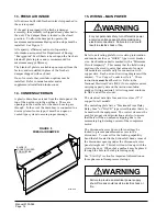
Figure 3
Internal Filter Access Through Upper
Service Door .................................................. 8
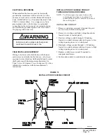
Figure 4
Mounting Instructions .................................... 9
Figure 5
Combustible Clearance ............................... 10
Figure 6
Wall Mounting Instructions .......................... 11
Figure 7
Wall Mounting Instructions .......................... 11
Figure 8
Common Wall Mounting Installations ......... 12
Figure 9
Fresh Air Damper ........................................ 14
Figure 10 Installation of Flexible Conduit .................... 16
Figure 11 Low Voltage Wiring ...................................... 17
Figure 12 Gas Pipe Connection .................................. 18
Figure 13 Proper Piping Practice ................................ 19
Figure 14 Lighting & Shutdown Instruction Label ....... 26
Figure 15 Top View of Gas Control .............................. 27
Figure 16 Sequence of Operation – Electronic
Blower Control ............................................. 29
Figure 17 Furnace Control Board & Blower Control .... 30
Figure 18 460V Blower Motor Wiring Options ............. 31
Figure 19 Fan Blade .................................................... 37
Figure 20 Low NOx Insert ............................................ 37
TABLES
Table 1
Specifications ................................................. 4
Table 2
Minimum Installation Clearances ................. 13
Table 3
Thermostat Wire Size ................................... 16
Table 4
Wall Thermostat & Subbase Combinations . 16
Table 5
Length of Standard Pipe Threads ................. 19
Table 6
Gas Pipe Sizes – Natural Gas ..................... 19
Table 7
High Altitude Derate Charts – U.S.
Installations Only .......................................... 22
Table 8
High Altitude Derate Charts – Canadian
Installations Only .......................................... 23
Table 9
WG421 Indoor Blower Performance ............. 32
Table 10 WG482 Indoor Blower Performance ............. 33
Table 11 WG601 Indoor Blower Performance ............. 34
Table 12 Integrated Furnace & Blower Control
Operation ...................................................... 35
Table 13 Cooling Pressure Table ................................. 36
Table 14 Refrigerant Charge ........................................ 36
Table 15 Fan Blade Dimension ................................... 37
Page
Page
ii.
Содержание WG421
Страница 8: ...Manual 2100 365 Page 5 MIS 1352 FIGURE 1 UNIT DIMENSIONS...
Страница 12: ...Manual 2100 365 Page 9 FIGURE 4 MOUNTING INSTRUCTIONS MIS 1472...
Страница 15: ...Manual 2100 365 Page 12 FIGURE 8 COMMON WALL MOUNTING INSTALLATIONS MIS 1474...
Страница 20: ...Manual 2100 365 Page 17 FIGURE 11 LOW VOLTAGE WIRING MIS 1162...
Страница 21: ...Manual 2100 365 Page 18 FIGURE 12 GAS PIPE CONNECTION MIS 1478...
Страница 29: ...Manual 2100 365 Page 26 26 LIGHTING AND SHUTDOWN INSTRUCTIONS FIGURE 14 INSTRUCTION LABEL...
Страница 34: ...Manual 2100 365 Page 31 FIGURE 18 460 VOLT BLOWER MOTOR WIRING OPTIONS MIS 1487 A B C...
Страница 41: ...Manual 2100 365 Page 38...
Страница 42: ...Manual 2100 365 Page 39...
Страница 43: ...Manual 2100 365 Page 40...
Страница 44: ...Manual 2100 365 Page 41...
Страница 45: ...Manual 2100 365 Page 42...
Страница 46: ...Manual 2100 365 Page 43...
Страница 47: ...Manual 2100 365 Page 44...
Страница 48: ...Manual 2100 365 Page 45...
Страница 49: ...Manual 2100 365 Page 46...
Страница 50: ...Manual 2100 365 Page 47...
Страница 51: ...Manual 2100 365 Page 48...
Страница 52: ...Manual 2100 365 Page 49...


