Manual 2100-587J
Page
34 of 59
and generator power didn’t cause a problem.
The units lost power, shut off and came back on
line normally. With the introduction of almost
instantaneous transfer switches, the millisecond long
power glitch can be enough that the compressor will
start to run backwards. In this scenario, the CCM will
catch this and restart the units normally.
26. PHASE MONITOR
All units with three phase scroll compressors are
equipped with a three phase line monitor to prevent
compressor damage due to phase reversal.
The phase monitor in this unit is equipped with two
LEDs. If the “Y” signal is present at the phase monitor
and phases are correct, the green LED will light.
If phases are reversed, the red fault LED will be lit and
compressor operation is inhibited.
If a fault condition occurs, reverse two of the supply
leads to the unit. Do not reverse any of the unit factory
wires as damage may occur.
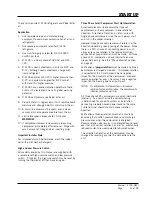
Optional Low Ambient Control
An optional low ambient control is available for both
factory- and field-installed options. The low ambient
control is to be applied to the WG3S/WG4S/WG5S
models when operation below 50° F outdoor conditions
are anticipated. Without this device, the evaporating
pressure would fall off, and the indoor coil would ice
over.
The fan cycling control cycles the fan motor on, once
the liquid refrigerant pressure reaches 350 psig, and
off, once it has dropped to 225 psig. It will continue
to cycle between these parameters depending on
outdoor temperatures and the load/stage of the system.
This cycling maintains a minimum liquid pressure
affecting the minimum suction pressure. This effect
insures an evaporating temperature that is slightly
above the point of ice formation on the evaporator.
Содержание WG Series
Страница 11: ...Manual 2100 587J Page 11 of 59 FIGURE 2A Mounting Instructions for WG3S2...
Страница 12: ...Manual 2100 587J Page 12 of 59 FIGURE 2B Mounting Instructions for WG4S2 and WG5S2...
Страница 14: ...Manual 2100 587J Page 14 of 59 FIGURE 4 Wall Mounting Instructions FIGURE 5 Wall Mounting Instructions...
Страница 15: ...Manual 2100 587J Page 15 of 59 FIGURE 6 Common Wall Mounting Installations...
Страница 25: ...Manual 2100 587J Page 25 of 59 FIGURE 11 Gas Pipe Connection...

