Manual 2100-587J
Page
19 of 59
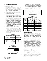
Electrical Grounding
When installed, the furnace must be electrically
grounded in accordance with local codes or in the
absence of local codes, with the National Electrical
Code, ANSI/NFPA 70, or Canadian Electrical Code,
CSA22.1, latest edition. Use a copper wire from
green ground wire on the furnace to a grounded
connection in the service panel or a properly driven
and electrically grounded ground rod. See Table 1
for proper ground wire size.
WARNING
Failure to provide a proper electrical ground
could result in electric shock or fire.
Field-Installed Equipment
Wiring to be done in the field between the furnace
and devices not attached to the furnace, or between
separate devises which are field installed and located,
shall conform with the temperature limitation for
Type T wire {63° F rise (36° C)} when installed in
accordance with the manufacturer’s instructions.
Installation of Flexible Conduit Through Return Air
Opening
NOTE: To allow proper clearance between the control
panel and any vent options, 90° conduit
fittings must be used on the back of the
control panel.
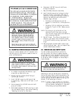
Installing Conduit
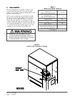
(see Figure 9)
1. Remove conduit access panel if required to gain
access to area behind control panel.
2. Remove low voltage and high voltage knockouts
located in rear of control panel.
3. Run low voltage conduit through 7/8 bushing
located in conduit entrance plate and secure to low
voltage opening in rear of control panel.
4. Run high voltage conduit through 1-3/4 bushing
located in conduit entrance plate and secure to
high voltage opening in rear of control panel.
5. Replace conduit access panel if required to
complete installation.
6. Seal around conduit in conduit entrance plate.
FIGURE 9
Installation of Flexible Conduit
WARNING
Failure to provide an electrical power supply
shut off means could result in electric shock
or fire.
Содержание WG Series
Страница 11: ...Manual 2100 587J Page 11 of 59 FIGURE 2A Mounting Instructions for WG3S2...
Страница 12: ...Manual 2100 587J Page 12 of 59 FIGURE 2B Mounting Instructions for WG4S2 and WG5S2...
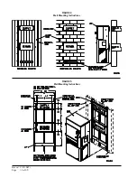
Страница 14: ...Manual 2100 587J Page 14 of 59 FIGURE 4 Wall Mounting Instructions FIGURE 5 Wall Mounting Instructions...
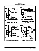
Страница 15: ...Manual 2100 587J Page 15 of 59 FIGURE 6 Common Wall Mounting Installations...
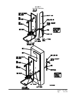
Страница 25: ...Manual 2100 587J Page 25 of 59 FIGURE 11 Gas Pipe Connection...

