5
8. Measure Distance to Tip Location
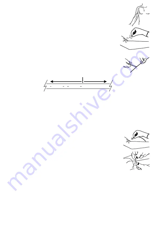
A. Using fluoroscopic control, determine the correct catheter length by advancing the guidewire to the
desired catheter tip location in the Superior Vena Cava (SVC).
B. Once the guidewire tip is in proper position, mark the length by clamping forceps onto the guidewire
at the skin site.
9. Removing Dilator and Guidewire
A. Rotate locking collar of dilator to remove dilator from sheath.
Caution: Do not withdraw dilator from microintroducer sheath until sheath is within vessel to
minimize the risk of damage to sheath tip.
B. Withdraw the dilator and guidewire, leaving the small sheath in place.
WARNING: Place a finger over the sheath opening to minimize blood loss and risk of air
aspiration. The risk of air embolism is reduced by performing this part of the procedure with the
patient performing the Valsalva maneuver until the catheter is inserted into the sheath.
10. Modification of Catheter Length
Note: Catheters can be cut to length if a different length is desired due to patient size and desired
point of insertion according to hospital protocol. Catheter depth markings are in centimeters.
WARNING: For PowerPICC SOLO
2
® FT catheters, do not trim the catheter shorter than 30 cm or in
the “NO TRIM ZONE” of the catheter shaft. Trimming shorter than 30 cm could result in catheter tip
displacement while power injecting.
20
NO TRIM ZONE
25
NO TRIM ZONE
30 • • • • 35 • •
DO NOT TRIM
TRIMMING AREA
A. Measure the distance from the insertion site (zero mark) to the desired tip location.
B. Using the guidewire to indicate desired length, retract the stylet behind the point the catheter is to be cut (if applicable).
C. Using a sterile scalpel or scissors, carefully cut the catheter according to institutional policy if necessary.
Caution: The stylet or stiffening wire needs to be well behind the point the catheter is to be cut. NEVER cut the stylet or
stiffening wire.
D. Inspect cut surface to assure there is no loose material.
E. Re-advance the stylet to the distal end of the trimmed catheter (if applicable).
WARNING: Ensure that the stylet tip does not extend beyond the trimmed end of the catheter. Extension of the stylet
tip beyond the catheter end may result in vessel damage, stylet damage, difficult removal, stylet tip separation, potential
embolism and/or risk of patient injury.
11. Insert and Advance the Catheter
A. Position the arm at a 90° angle, maintaining sterility.
B. Insert the catheter (and stylet, if applicable) into the microintroducer sheath.
C. Advance the catheter slowly.
D. Stabilize the catheter position by applying pressure to the vein distal to the microintroducer sheath.
E. Withdraw the microintroducer sheath from the vein and away from the site.
F. Split the microintroducer sheath and peel it away from the catheter.
Caution: Do not pull apart the portion of the sheath that remains in the vessel. To avoid vessel
damage, pull back the sheath as far as possible and tear the sheath only a few centimeters at a
time.
12. Complete Catheter Insertion
A. Continue to advance the catheter. For central placement, when the tip has advanced to the shoulder, have the patient turn
head (chin on shoulder) toward the insertion side to prevent possible insertion into the jugular vein.
Note: The PowerPICC SOLO
2
® catheter features a reverse-taper catheter design. Resistance may be felt approximately
7 cm distal of catheter hub when introducing the catheter into the sheath due to an increase in outer diameter (O.D.)
The introducer may be partially split, but not removed to facilitate insertion of the catheter past this point if necessary.


